144MHz Activity Report CdF 2018
(2018-06-03) PE1ITR
In the first full weekend of june (2-3/6) I was qrv on 144MHz during our national fieldday contest and the Concour de France.
The main purpose was to try my new 2 meter amplifier. I used a medium setup station. The antenna was 9 elements yagi 6 meters above the ground fixed to 210 degrees azimut.
It was fun to search the band for distance signals. On saturday the tropo radio propagation was medium. Saturday evening I heard F6KNB at 848 km distance with a weak tropo / airplane scatter signal calling, but they couldn't catch my call. But on sunday morning the tropo was much better and the qso with F8KNB was easy made. At the end of the contest there was a E-skip opening on 144MHz and I could work 4 EA stations. My mind went into E-skip mode and I didn't realised some EA stations where also in contest. So in the speed of the QSO i didn't gave a contest serial number except the last E-skip QSO. Sri to the other stations.
QSO MAP

Fig 1: Polar map for 144 MHz
  TOP 10 DX QSOs:
-------------------
EA4LU         IM68TV 1666 km
EA4YR         IM78BX 1637 km
EA1ASC        IN70DX 1438 km
EA1BYA        IN70WW 1375 km
F6KNB         IN94UT  847 km
TM5G          IN97EA  706 km
TM2OP         JN06JG  664 km
F1NZC         JN15MR  657 km
F6KJX         JN07QO  514 km
F6KCZ/P       IN99PI  489 km
Station setup
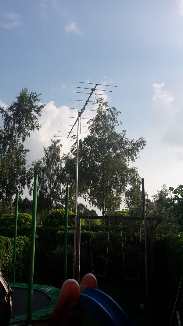
Fig 2: antenna 9el dk7zb yagi 6 meters above ground fixed to 210 degrees azimut
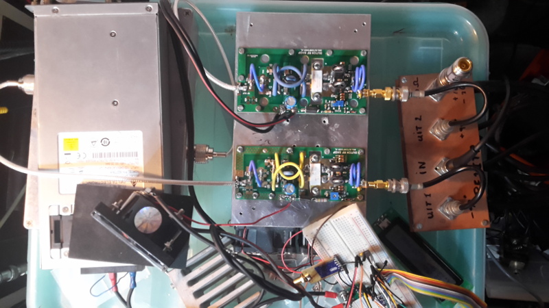
Fig 3: experimental setup of the SSPA. 2x MRFE6VP6300H.
The picture shows the experimental SSPA setup used this weekend. On the heatsink two seperate amplifiers with a MRFE6VP6300H fet. On the right the 5 or 6 watt signal is splitted with a rate race to each SSPA input. Each SSPA gets 2.5 watts.
The outputs of the amplifiers is combined with a rate race 75 ohm coax construction. The combiner is on the left of the amplifiers below the power supply. Directly at the combiner I measure a little over 600 watts. From the combiner the signal goes to a lowpass filter, coax relay, coax to antenna. At the antenna there will be around 400 watts left.
On top of the combiner is the power supply of 48v 21 amp. The breadboard below the ampifiers is the experimental setup of the control board. An arduino will measure the input current, input power, forward and reflected power. If the measured values are out of range the power supply will be disabled.
Thanks for the qso's and cu next year.
73 Rob PE1ITR
HOME | Go Back