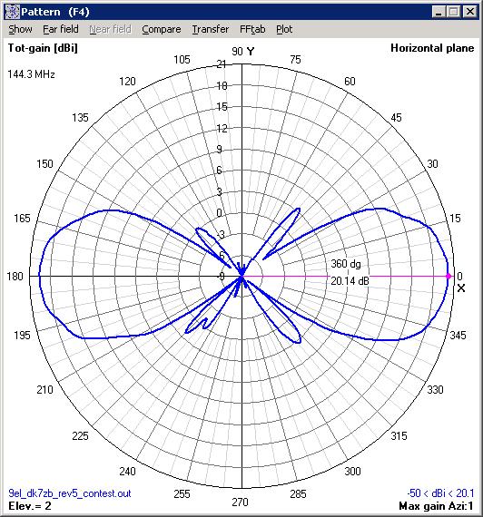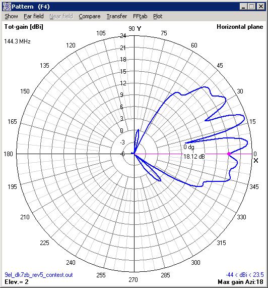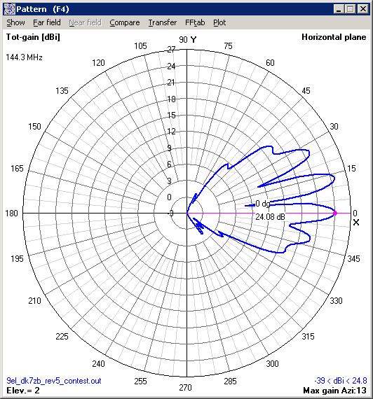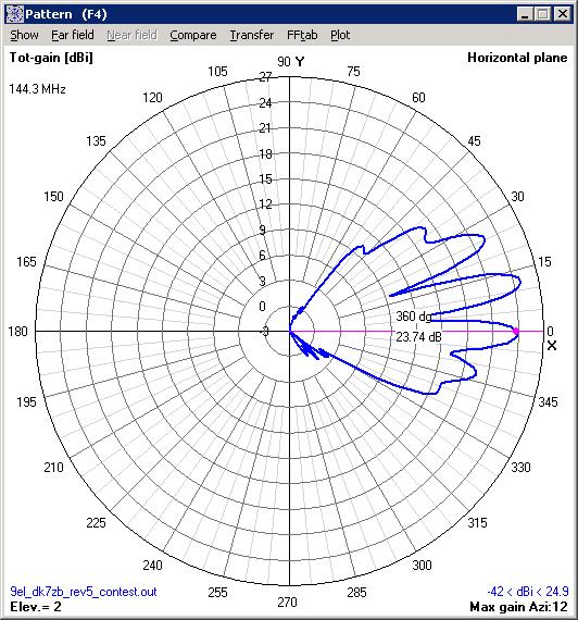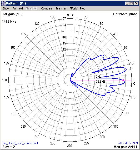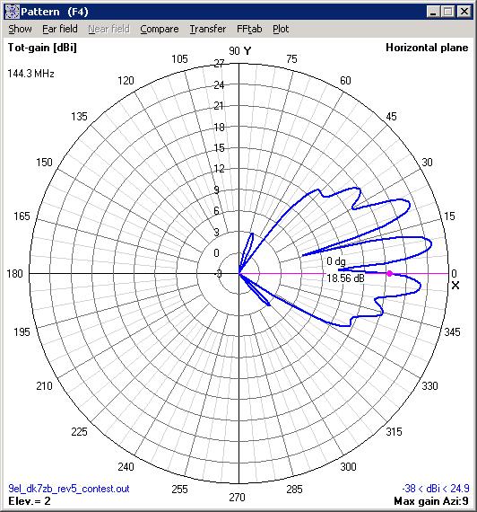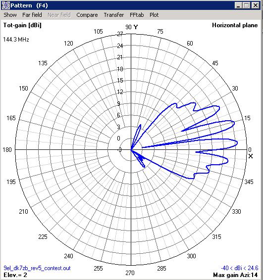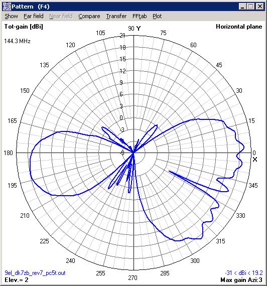
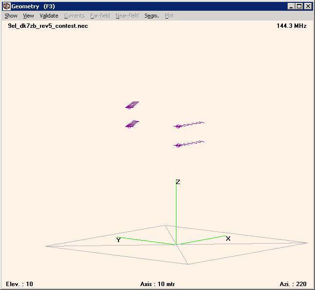
| Performance | 15,49dBi @ 144.300MHz |
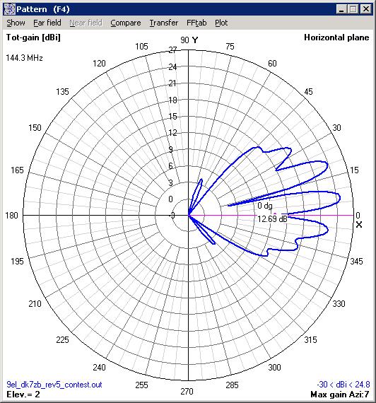
| Peak Gain | 15.49dBi |
| Peak F/B | 34dB |
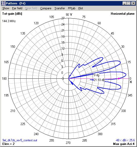
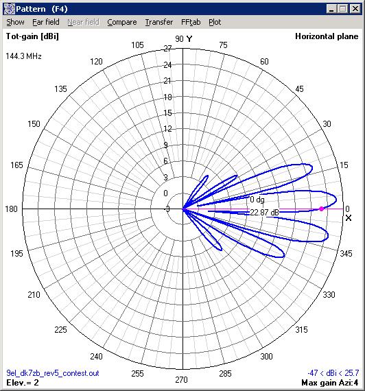
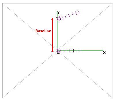
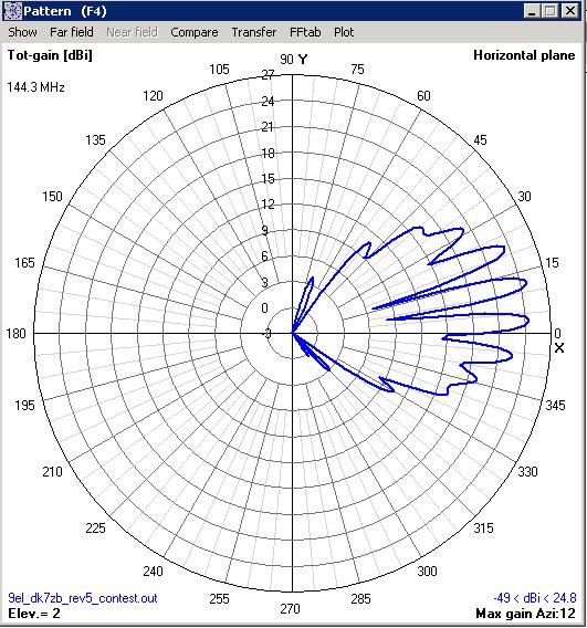
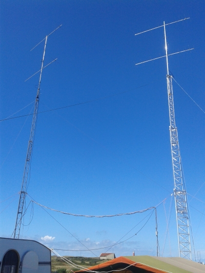
| Stacking Distance | 3.4m (3.5 recommended) |
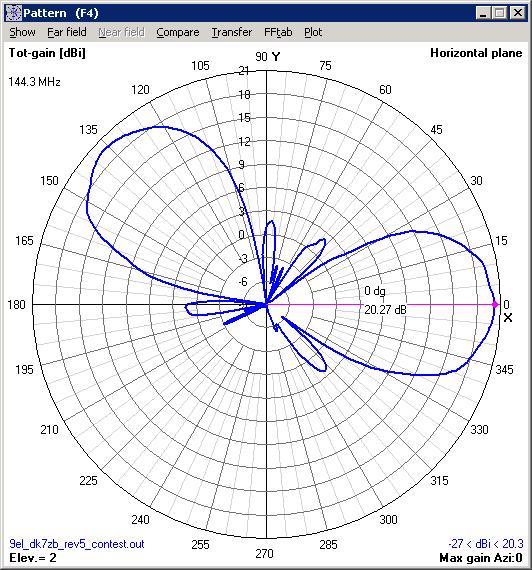
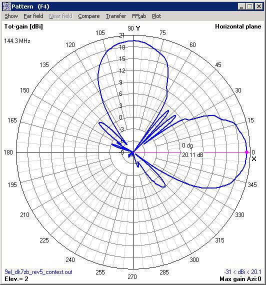
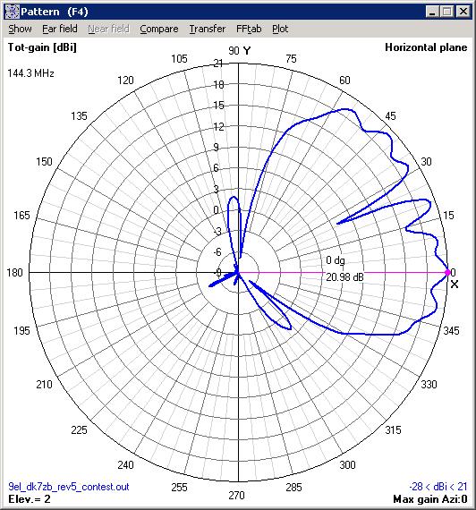
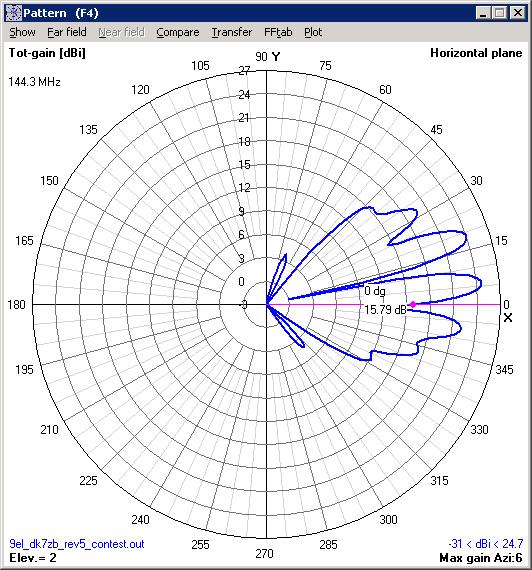
| 2 Stacked Gain @ 3.4m spacing | 17,63dBi |
| 2 Stacked F/B | 27.96dBi |
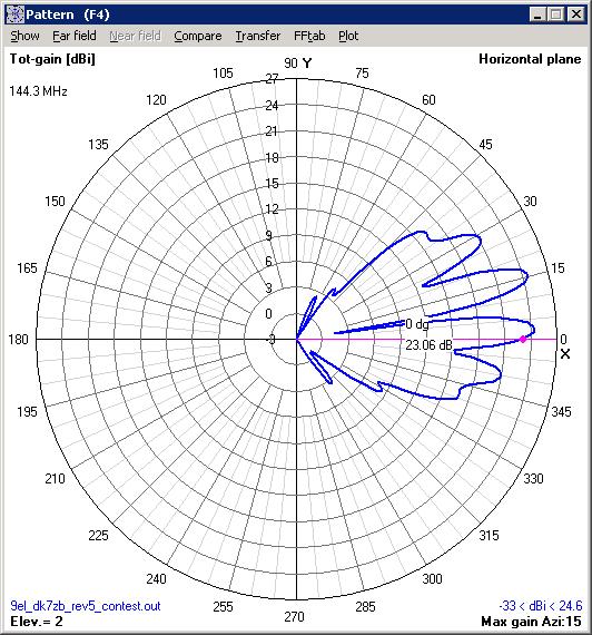
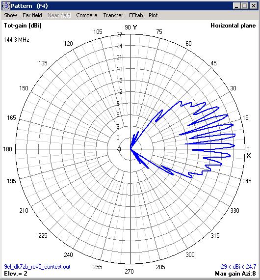
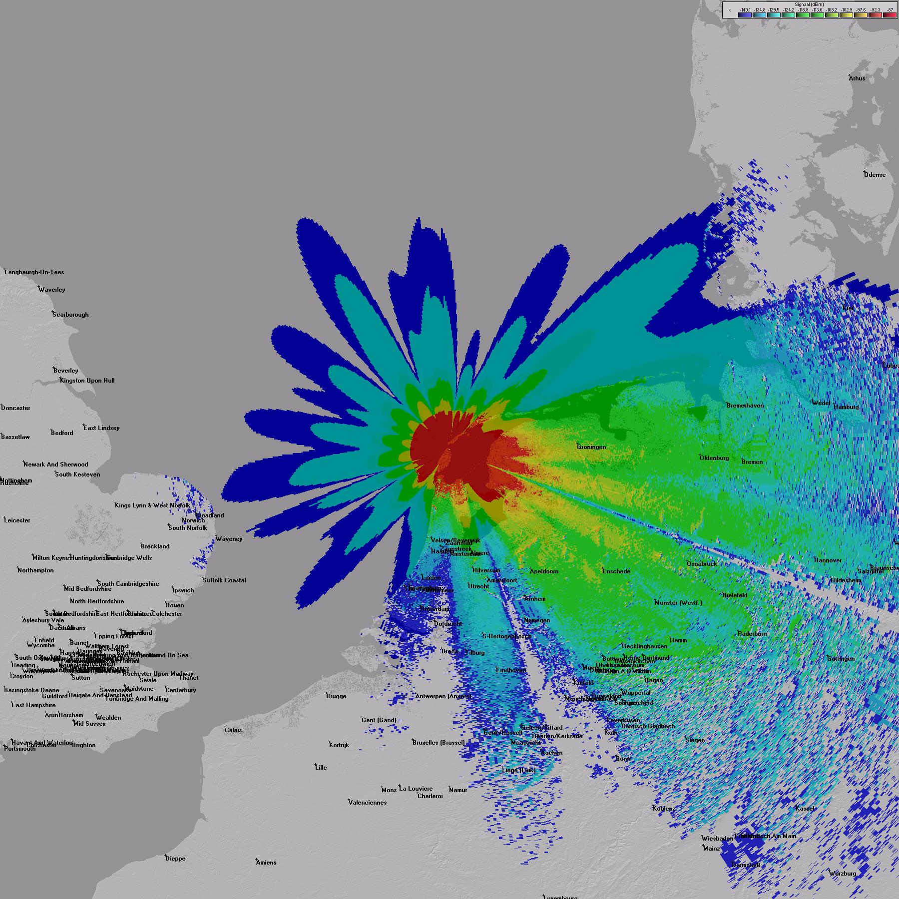
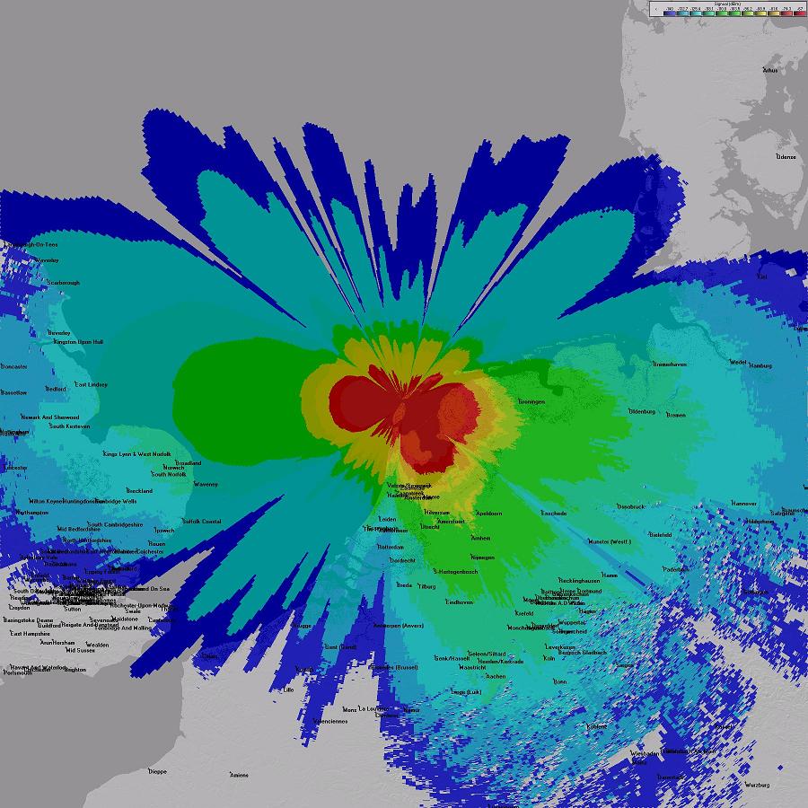
| Peak Gain Above Ground | 21.15dBi @ 15m AGL @ 2 degrees elevation |
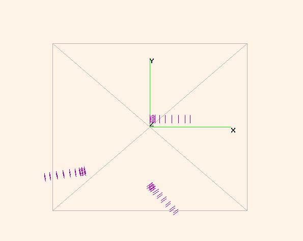
| Boom Lenght | 4.980m |