51.7 MHz DATV (part 2)
(2023-07-16) PE1ITR
This webpage is a status update about my 51.7 MHz RB-DATV station. The first experiments in the 6 meter band started in 2020 and can be found on this webpage. Recently I picked up the thread again and improved the whole setup considerably.
In the meantime, frequencies have also been designated for DATV in the IARU-R1 band plan. The band plan specifies frequencies for various DVB bandwidths. Here in the region we use 51.7 MHz. The most used mode is DVB-S(2) with a symbol rate of 125ks.
The 50 MHz band is interesting for DATV DX in every respect. Various propagation mechanisms are possible to bridge large distances. In the month of June can benefit from E-skip propagation. The band also seems very suitable for tropo and aircraft scatter QSOs. And maybe it's possible to make meteor scatter DATV qso's. I have often experienced reflections of 20 to 30 seconds with good signal strength. For DATV we need at least 4 seconds for an image. I think it's worth trying.
The path losses for AS or TS are about 10 db less compared to the 144 MHz band. We can benefit from this if we build a well-equipped DX station as we also use on the 2m band. We have to take into account that the antenna gain is quickly 3db or less compared to a 2m beam. Later in this page it will be shown that the antenna must be placed sufficiently high off the ground for a low take-off elevation angle. This is important for TS/AS propagation DX.
Particularly unfortunate is that, in my opinion, unnecessarily low power restrictions have been imposed by the government within the 6m band. I am aware that on 6m the DATV activity takes place in the frequency band parts where the amateur service has secondary status.
I will only be in a portable setup QRV with the large antenna. I don't have room for this in the home situation. On July 14th, 2023 I made my first DATV QSO at 51.7 MHz over 58 km distance with this setup. This was a two-way QSO with ON7MOR. So I am ready...
Station Setup
The entire DATV transmitter/receiver consists of 3 boxes. There is a box for the transmitter with receiving converter. This box also provides the sequenced PTT signals for switching the power amplifier and pre-amp coax relay. Then there is a separate box for the PA with the 2x MRF300 in the final stage. And there is a separate box with the coax relay and pre-amplifier. This is shown in the block diagram below.
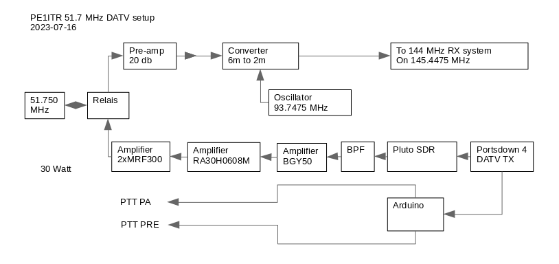
The reception converter is an old build from the late eighties with a BF900 and SBL-1 mixer. I happened to have the 93.747 MHz crystal laying around. This brings the signal to 145.447 MHz which then goes to my standard DATV setup for 2m as I described here before.
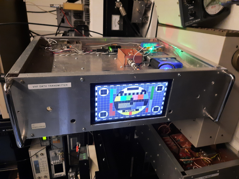
Transmitter and Converter Box
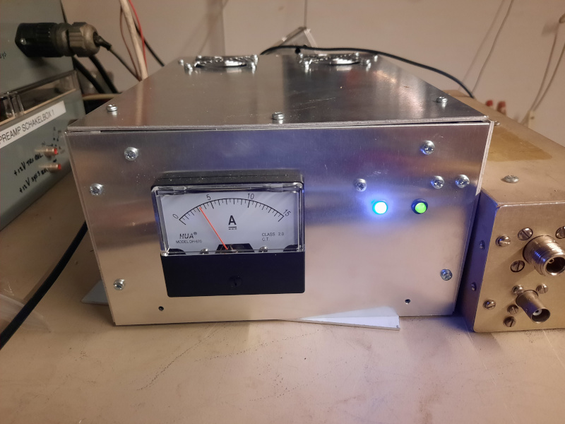
Amplifier Box
Antenna
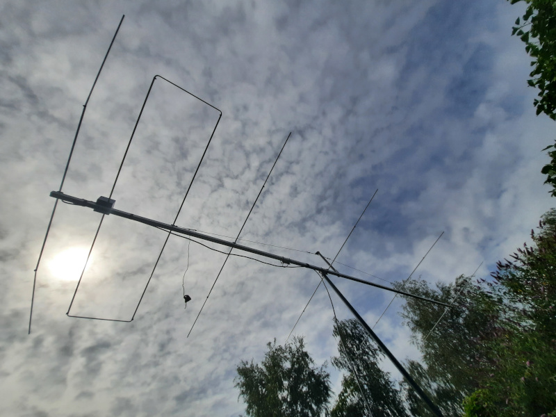
I converted a commercial 6el LFA 2 antenna for 50.150 MHz to 51.7 MHz. This antenna is nearly 7 meters long. With the 40 mm boom a bit heavy antenna for portable use, but I'll do with it.
I have improved the feed point of the dipole and provided it with an N connector so that it is faster to connect. All elements have been shortened by 40mm on each side so that the antenna is suitable for 51.7 MHz. This was easy to achieve because the element tips are held in place with hose clamps and the length is easy to adjust. The boom gui construction has also been slightly changed so that it is a permanent part of the boom.
Simulations with NEC4 shows the antenna performance. In my portable setup I use a mast of 6m high. I plotted the beam elevation angle for this situation. The beam angle is also plotted for the situation that I am standing on a hill. A low beam angle is important for DX. Its important for Tropo DX that I have a location on a hill. I have made a table in which the loss is plotted against the height.
antenna
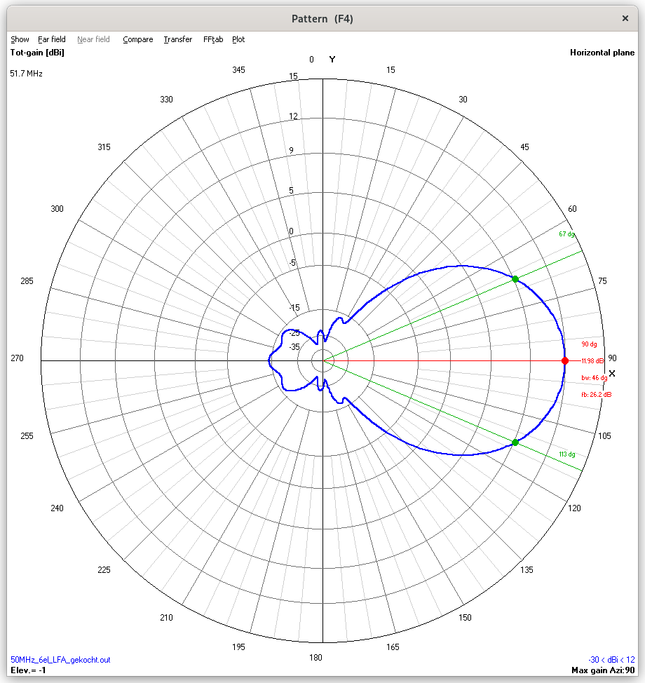
Horizontal pattern free space.
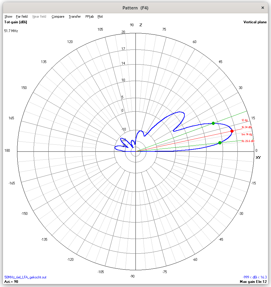
Vertical pattern 6m above ground. 1st lob elevation angle is 12 degrees. This is not good for Tropo DX.
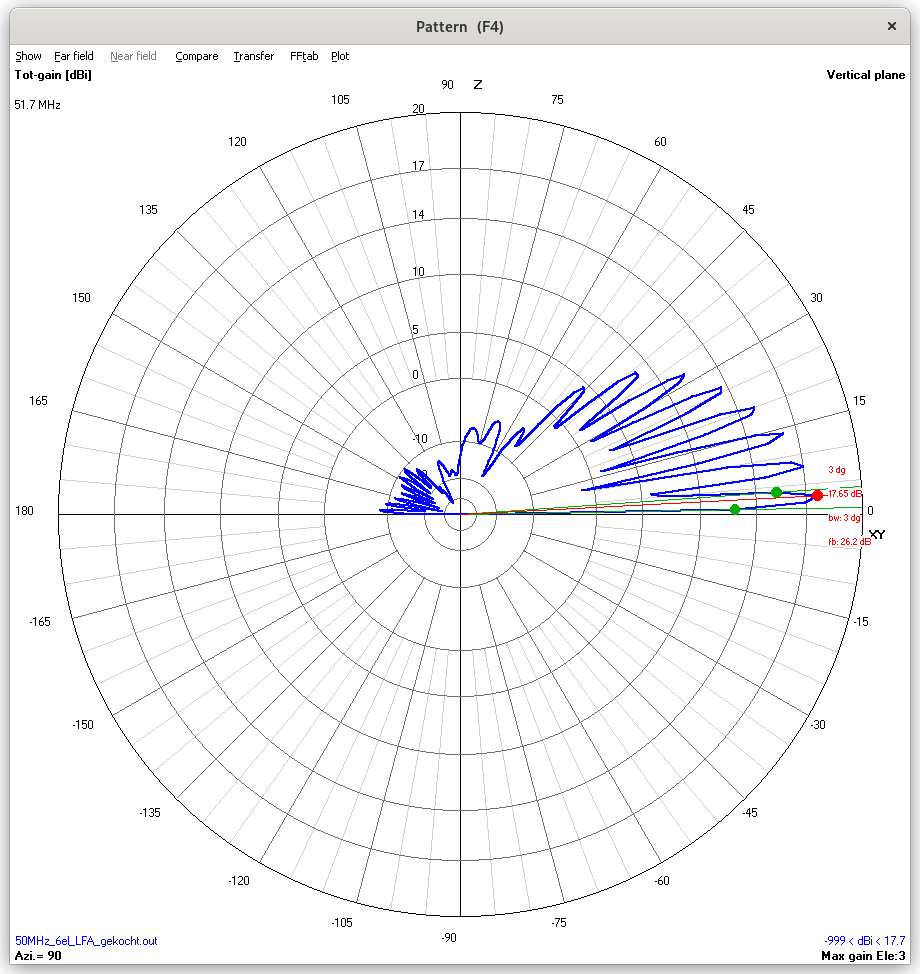
Vertical pattern on hilltop cq at 27m height. 1st lob elevation angle is 3 degrees. Good for Tropo DX.
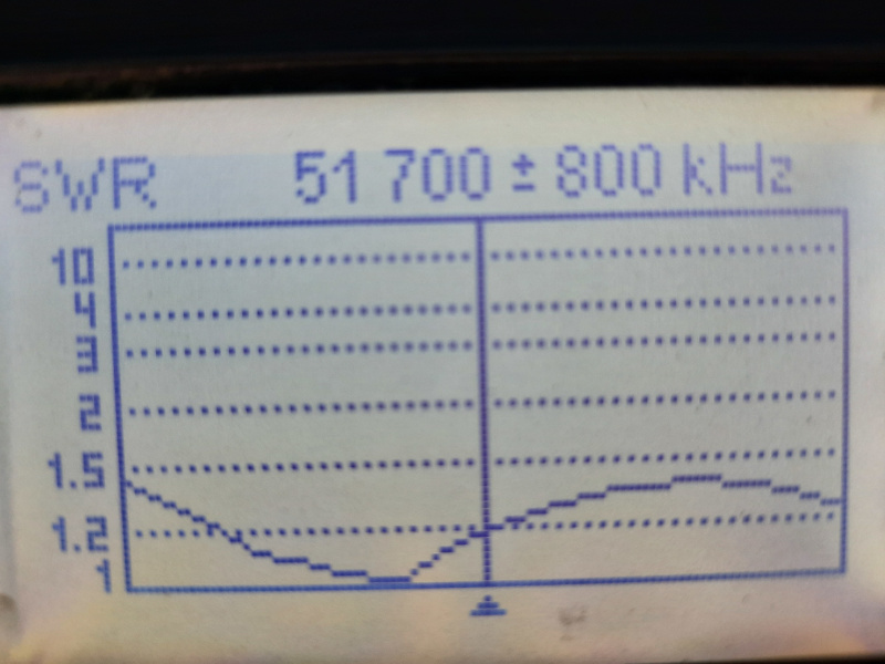
swr
Height versus link loss
The antenna must be at least 2.5 wavelength if not higher above the ground. The table below shows the effect of the height in relation to the link loss. I assume a take-off elevation angle of 3 degrees is good enough.
| Height AGL (m) |
Gain first lob (dbi) |
Gain at 3 degr. elev. (dbi) |
Extra link loss (db) |
| 30 |
17.54 @ 3 degrees |
17.54 |
0 |
| 20 |
17.61 @ 4 degrees |
16.89 |
-0.54 |
| 10 |
17.15 @ 9 degrees |
12.41 |
-5.02 |
| 6 |
16.32 @ 12 degrees |
8.26 |
-9.17 |
| 3 |
16.44 @ 20 degrees |
2.74 |
-14.69 |
Two-way QSO
PE1ITR (JO21QK) 2023-07-14 20:04 UTC 51.7 MHz ON7MOR (JO21GK) D4 D3 DVB-S2 125ks FEC1/2 - 58km Distance
ON7MOR used a Moxon antenna 12m above the ground. PE1ITR a 6el LFA at 3m above the ground.
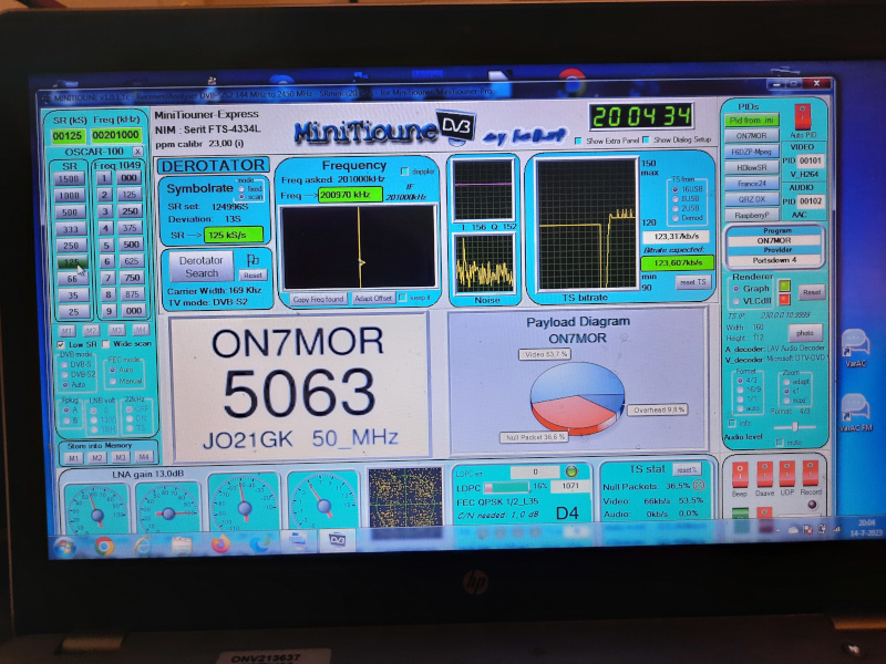
Signal of ON7MOR at PE1ITR
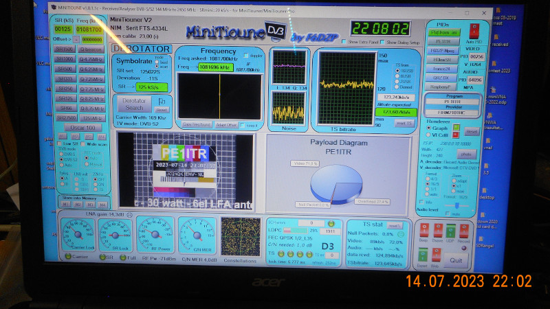
My Signal PE1ITR at ON7MOR
HOME | Go Back