Horizontal polarized omni directional 50MHz Antenna
(2013-05-02) PE1ITR
This page are design notes in my search for a suitable 50MHz horizontal polarized omni direction 50MHz antenna.
This antenna is intented to use in a contest station as a second system beside the stacked yagi beam system.
An omnidirectional systeem can be an advantage when it comes to short openings on wich the operator must react quickly.
Further more the presence on the band can be improved. This all to make more qso's.
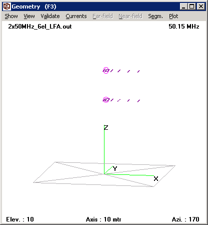
The directional antenna
The directional antenna is intended to direct the beam. And because the antenna height the beam has a low tak-off angle.
This is good for the long distance qso's.
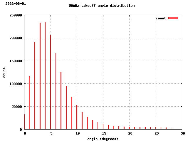
Fig: This shows the distribution of the angle of incoming signals based on clusterspot qso's and Es progation. Most signals are arriving around 3 or 4 degrees.
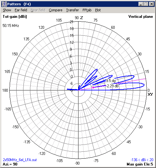
The main beam has its takeoff angle at 5 degrees. So a little bit above the needed angle. Its best that the omni dir antenna serves the part between 5 and 12 degrees elevation.
The main beam has a gap at 9.5 degrees. There are nearly no qso's above 12 degress elevation.
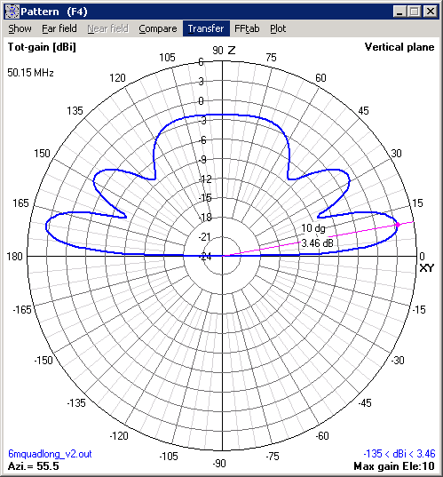
4 quadlong antenna to 4 directions
I have seen this inspiring setup at another contest station. I was thinking could the same be done in another setup: less complicated,
the possibility of Z-axis control, more or less the same gain and a more round horizontal pattern.
4 DK7ZB quadlong antenna's
8 meter above ground
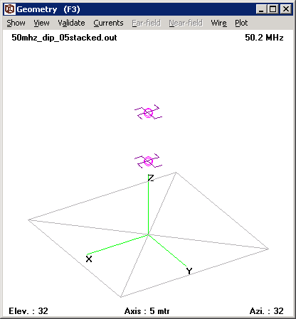
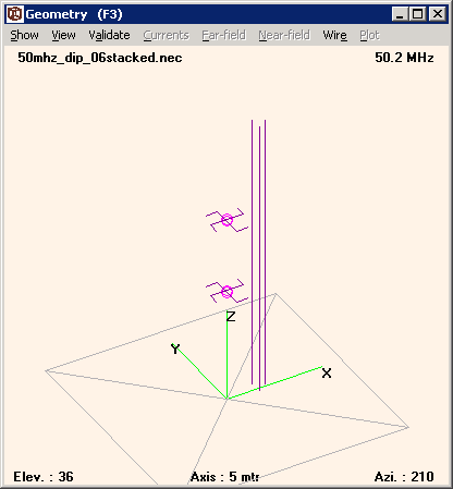
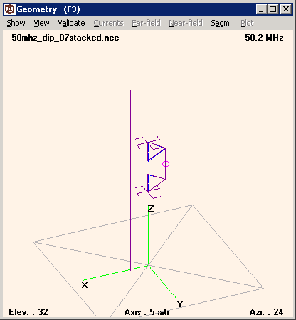
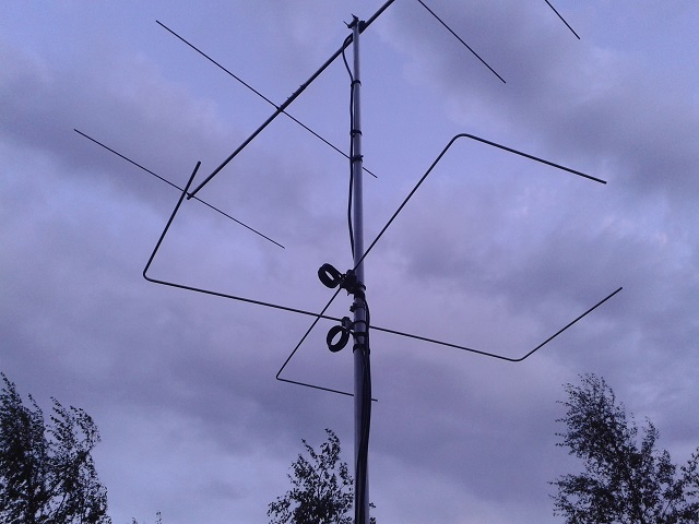
2 stacked omni directional dipole antennas
2 stacked dipoles with bended dipole
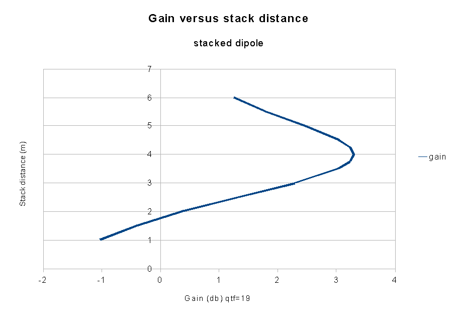
4 meter stack distance
6 meter above ground (lowest dipole)
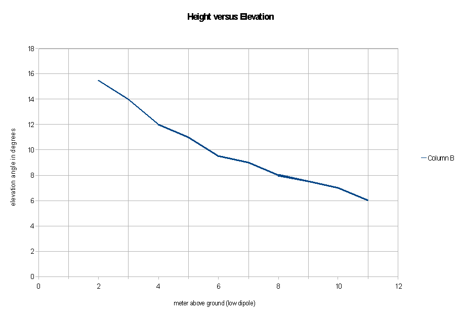
Fig: Optimum stacking distance is 4m meter
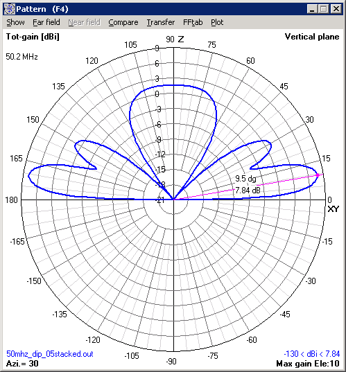
Fig: Takeoff angle between 9 and 10 degrees looks good because it fills in the gap op the
high gain antenna and the first hop will arrive at dense populated area. The lowest antenna must be
at 6 meters above ground. The upper antenna will be at 10 meters above ground.
Based on the the arriving angle distribution graph the omni must serve the 5 to 10 degrees takeoff angle.
In this case the upper antenna must be 14 meters above ground.
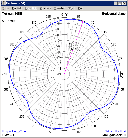
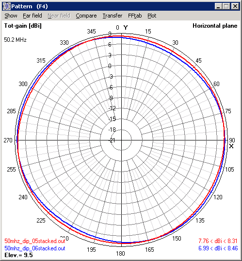
Influence of the mast on horizontal pattern
Fig: The blue line is the horizontal pattern with mast. The red line is without mast.
The mast makes the pattern more eleptical.
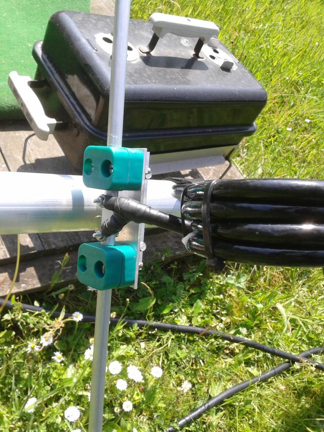
Feeding the dipoles
The Feeder is made of 50 Ohm ecoflex 10 and 75 Ohm cable tv coax. Total lenght to the main splitter must be around 2m.