Aircraft Scatter
(2010-12-15) PE1ITR
Many radio links between the 500 and 800 km at VHF / UHF are made via airplane scatter. This page is a collection of experiments that these radio links are investigated. It is intended to be notes to myself.
Below a facinating picture of airplane reflections from the graves vhf radar.

Airplane reflections from HB9F (432.432MHz) received by PE1ITR
under construction
Contents
1. Experiment Setup
2. Correlation between airplane activity and reflections
3. Doppler and Receiver data
4. ADS-B data
1. Setup


2. Correlation between airplane activity and reflections
There is correlation between the airplane activity within the antenna beam and the signal levels.
The red line is receiver data and the other colors are ADS-B data.
Sometimes the peak is off 1 hour. It looks like the ADSB data has a UTC v local time issue.


3. Doppler shift and receiver data

The data from the receiver is put in a text file and imported into the database.
Example receiver data record:
Timestamp           Noise    Peak    Signal Freq
2010-11-30 00:01:00 -101.968 -83.072 18.897 16432704.2
2010-11-30 00:01:01 -103.643 -83.198 20.444 16432705.4
2010-11-30 00:01:02 -102.911 -83.884 19.027 16432704.8
2010-11-30 00:04:02 -103.599 -85.560 18.039 16432707.6
2010-11-30 00:04:03 -103.046 -84.032 19.014 16432707.6
2010-11-30 00:04:04 -103.025 -82.735 20.291 16432709.7
2010-11-30 00:04:05 -102.070 -83.139 18.930 16432709.7
2010-11-30 00:04:06 -103.246 -84.013 19.233 16432707.6
2010-11-30 00:04:07 -102.797 -81.813 20.984 16432707.4
2010-11-30 00:04:08 -103.924 -80.714 23.210 16432708.6
2010-11-30 00:04:09 -102.365 -80.378 21.987 16432707.8
2010-11-30 00:04:10 -102.052 -81.025 21.027 16432706.3
2010-11-30 00:04:11 -102.332 -82.200 20.132 16432706.1
2010-11-30 00:04:12 -103.235 -81.177 22.058 16432707.5
2010-11-30 00:04:13 -102.801 -81.337 21.465 16432707.3
2010-11-30 00:04:14 -103.183 -80.511 22.672 16432705.2
2010-11-30 00:04:15 -102.866 -82.012 20.855 16432705.1
2010-11-30 00:04:16 -101.912 -82.345 19.567 16432706.2
2010-11-30 00:04:17 -102.601 -82.605 19.997 16432705.4
2010-11-30 00:04:18 -102.392 -81.313 21.080 16432703.1
2010-11-30 00:04:19 -102.724 -83.305 19.418 16432703.0
Graph from doppler pattern
The state of zero doppler in the reflection path is defined on the line between transmitter and observer.
And on an eleptical lines between transmitter and oberver.
Below 2 graph with the zero doppler points calculated from the ADS-B data.


4. ADS-B data
Example ADS-B data record:
4CA4E8;EI-DPD;2010-11-30;00:57:22;RYR2HM;29325;455;52.6428;-4.2951;-1792;7553;0;299;B738;Boeing;Ryanair;
Reflections from airplanes
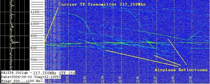
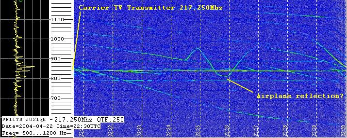
When testing the receiver it is tuned to a 217.250Mhz TV carrier. This are from airplanes.... Nice pictures.


HOME


