Angle of arrival
The map below shows the situation between PC5T and the position of most UK stations. The yellow dots are the midpoint between PC5T and a station. At 10 km altitude, the aircraft reflection takes place around these yellow points.The graph shows the distribution of the distances between PC5T and the stations. The most worked stations are located at a distance between 320 and 600 km. If we assume that the reflection point is at 10 km altitude at half this distance, the signals will come in between 4 and 1 degrees elevation.
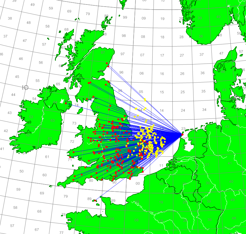
Situation between PC5T and most UK stations.
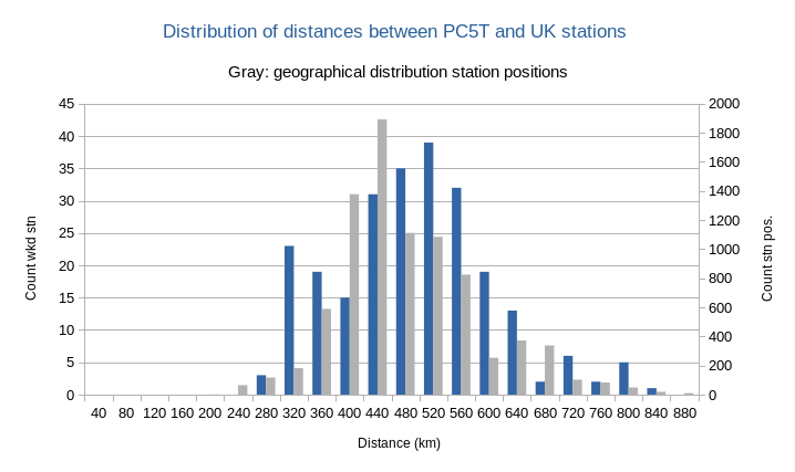
Blue bars: 320 km distance corresponds to 4 degrees elevation. 600 km distance corresponds to 1 degree elevation. Notice the dip at the 400 km distance.
The 400 km Dip
The dip around 400 km in the number of stations worked is striking. It could be because there are fewer stations geographically, or because of the antenna pattern. It turns out that in the last two years, between 390 and 410 km away, 224 locations have been activated in SSB/CW contest. This is significantly more than we have worked.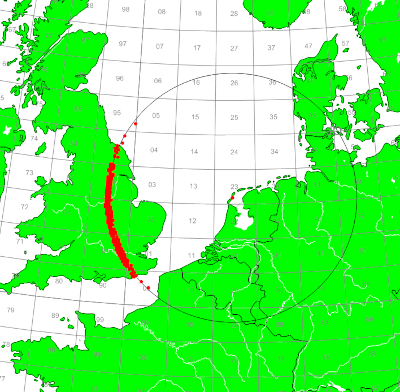
Between 390 en 410 km distance 224 stations are spotted in CW/SSB contests
Antenna Pattern
When a yagi antenna is low above the ground, it has a high elevation beam angle. The higher the antenna is, the lower this elevation beam angle is. This is a known effect on HF, but is also true on VHF. Simple Moonbounce stations at 6m and 2m also use this effect to create extra ground gain. The moon runs that through the first and second lobes.In the previous section it was established that the aircraft reflections enter between 1 and 4 degrees.
When we look at the vertical radiation pattern of the 3 stack antenna system, the first lobe is at 1.5 degrees and the second lobe is at 4.5 degrees. That is fine because it matches to the incomming signals. It also indicates that there is no real need for an extra low antenna. However, between the first and second lobe there is also a point at which the antenna is not sensitive. When aircraft reflections take place at a height of 10 km, this dip creates a dead zone. This zone is probably 400 km away.
We can improve the reception by placing an extra antenna at a height of 10 meters. At this height the beam angle is exactly 3 degrees and we can "fill in" the point between the first and second lobe of the 3 stack antenna system. This can be seen in the graph below.
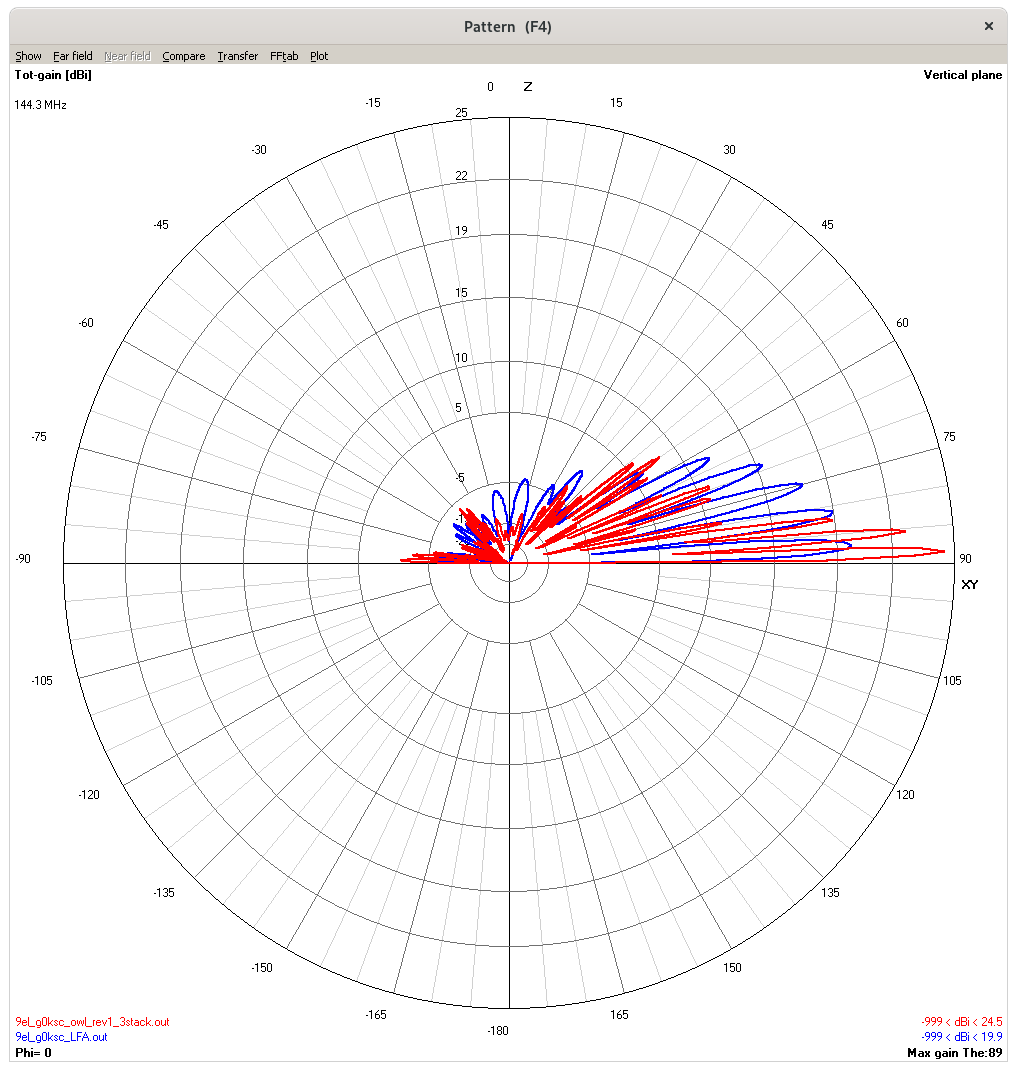
The red line is the vertical radiation pattern of the 3 stack as used in the west system. The blue line is the vertical radiation pattern of a single yagi at a height of 10m.
Stack Switch
On the HF bands it is common to use a stack switch with several antennas stacked one above the other. Antennas can be "removed" from the stack on this switch to adjust the beam angle in this way. You may wonder whether such a system is a solution to the problem on this webpage?This has been investigated in a simulation by feeding only the lower antenna instead of all three antennas. The difference can be seen in the graph.
It is clear to see that this has insufficient effect. The lower antenna is still too high.
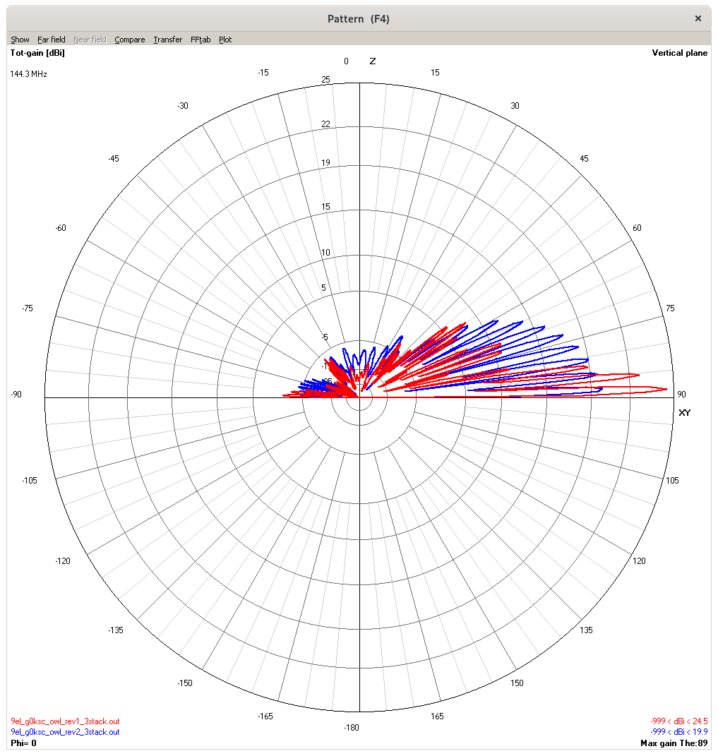
The red line is the pattern of the full 3 stack. The blue line shows the pattern when only the lower antenna is powered. The lower antenna is 16m high.
Final conclusion
An additional antenna low above the ground, up to 6m high, is of no use to improve the reception. The beam angle is then still too high. It makes sense to place an extra antenna to fill the dips between lobes of the 3 stack antenna system. This extra antenna must then be at a height of about 10 meters. It is estimated that this antenna for stations 400 km away can improve the signal strength by up to 10 dB.It seems worth trying this extra antenna.
HOME | Go Back