144MHz OWL Antenna converted to X-pol yagi
(2020-04-05) PE1ITR
On this page a description of how I converted my existing 9 elements OWL antennas to X-pol yagies. Successively the way in which the two yagies are placed on 1 boom. A few words about the orthogonality and the separation between the horizontal and vertical part of the antenna. The attachment to the mast. And the results of NEC simulations.
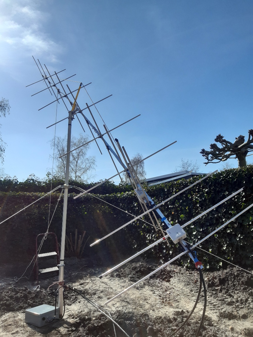
Fig 1: 9 elements OWL yagi .Test line-up 2020-04-04. Made 10 EME QSO during the ARI EME contest

Fig 2: 9 elements OWL yagi. Design View
Boom construction
I made a table in Excel and started to slide with the boom of the 2nd antenna until the elements do not coincide and the elements do not coincide with the clamps between the boom pieces. In the end I realized that the horizontal part should start 120 mm from the back of the tree. for the vertical part this is 554 mm.
It was only looked at from a constructional point of view. I will get the RF signals in phase with a delay lines made of pieces coaxial cable.
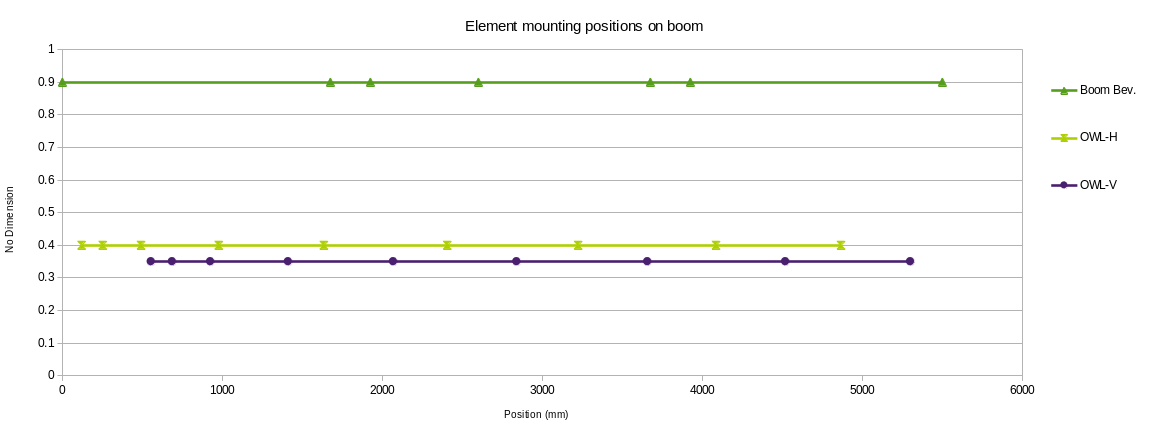
Fig 1: Arrangement of the elements on the boom.
Orthogonality
Orthogonality is about mutual coupling in cross Yagi antennas. In cross Yagis even small deviations from symmetry can cause fairly large transfers of power from one polarization to the other. Also in receive mode it is better that the two polarizations see each other as little as possible. This way there is a good channel separation. From the literature I understand that the channel separation between the horizontal and vertical part of the antenna better than 20 db is a reasonable value.
In NEC I performed a simulation of the Kruisyagi in which transmit power is set to 1 polarization. You can then calculate the power in the other dipole on the basis of the current and voltage values. At a certain power I pushed both dipoles outwards as if the tree is getting thicker. The graph shows that this increases the coupling between horizontal and vertical polarization.
In my yagi the dipoles and elements are about 19mm from the center of the dipole. According to the simulation, this would provide attenuation of -22 db between the two polarizations.
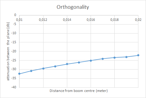
Fig 12:When the diameter of the boom is increasing the top mounted elements are shifting out of plane. This results in a higher coupling between the to planes.
I also measured the degree of coupling with a miniVNA in the setup as shown above in the photo. The measured value is then -24 db. This corresponds to the value from the simulation. I played around with metal objects near the antenna to get an idea of the influence on the coupling. Depending on where you keep a metal object, the coupling can become much stronger.
It is better to attach the antenna to the mast via a plastic tube. The NEC simulation also shows that there should be no metal objects within 1 meter around the antenna.
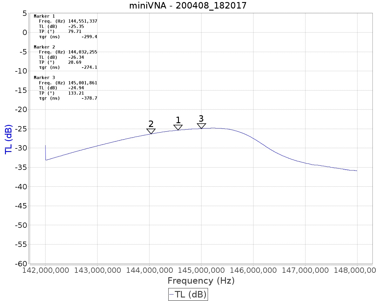
Fig 1: coupling -24 db
The graph below clearly shows that the coupling is greatest when the antenna is in resonance. Of course that's true.
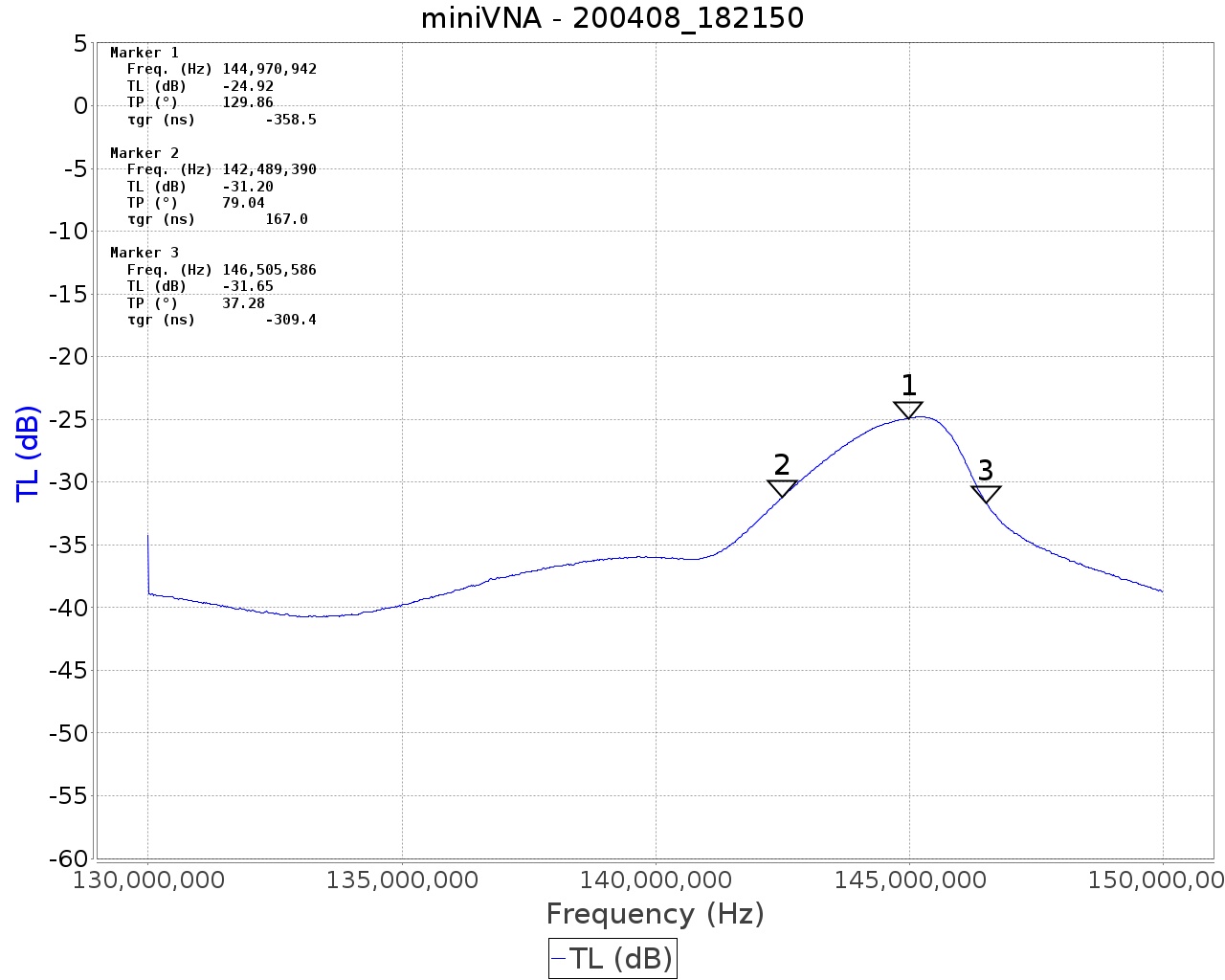
Fig 1: coupling
HOME | Go Back