23 elements yagi on 868 MHz (and 903 MHz)
(2021-08-03) PE1ITR
Preface
A few years ago I made an antenna for 868 MHz. In the Netherlands, this frequency is a license-free frequency for low power applications with a maximum of 25 mW e.r.p.. There is a lot of LORA activity. I made this antenna to be able to receive a number of LORA devices at some distance.
I got the design from an online internet yagi calculator. I don't know what algorithm was behind that, but judging by the return loss pattern, I think it was based on the DL6WU yagi design. The fact that you can break off the yagi at any length also points to that.
I knew from experience that the yagi worked, but had never really measured it.
Eventually this yagi ended up in the shed. Recently this yagi came to my attention again because in Region 2 the frequency band 902 - 928 MHz is an amateur radio band. It is also indicated by the 33 cm band. There is moonbounce activity just above 903 MHz. I was wondering if I could use this yagi to receive it. Regardless of whether the antenna gain of a single yagi is sufficient.
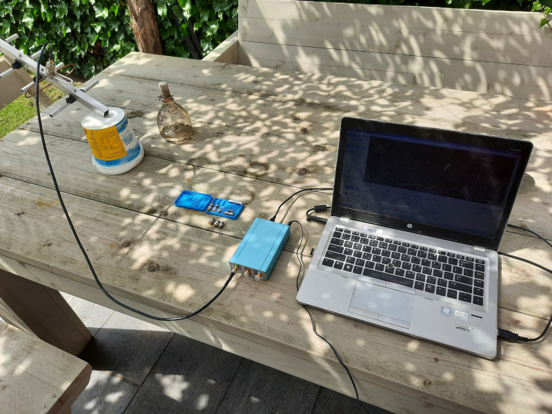
I also had recently gained access to a MegIQ VNA0460e covering 400 MHz - 6 GHz owned by the VERON VHF committee that I wanted to discover. At least it seemed like a nice afternoon project in the garden with which I could answer the questions about this antenna and get to know more about the VNA.
Questions to investigate
What is the return loss of this antenna between 800 and 1000 MHz?
Does this antenna also work on 903 MHz?
Design and build
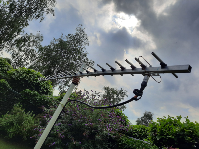
The antenna is constructed from 10mm thick aluminum elements. There are 21 directors and 1 reflector. The elements are fixed to the boom with plastic element holders and a 3mm bolt through the middle. The boom is 20x20mm.
The driven element is a folded dipole construction made of cupper wire. There is a 1 in 4 balun in it to transform the 200 ohm impedance in the feeding point to 50 ohms. The coax cable can be connected with an N connector.
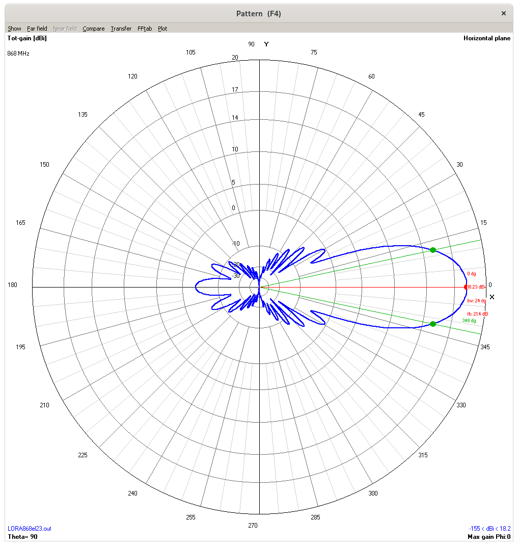
NEC simulation. Horizontal free space radiation pattern
Here is the NEC file.
Return loss
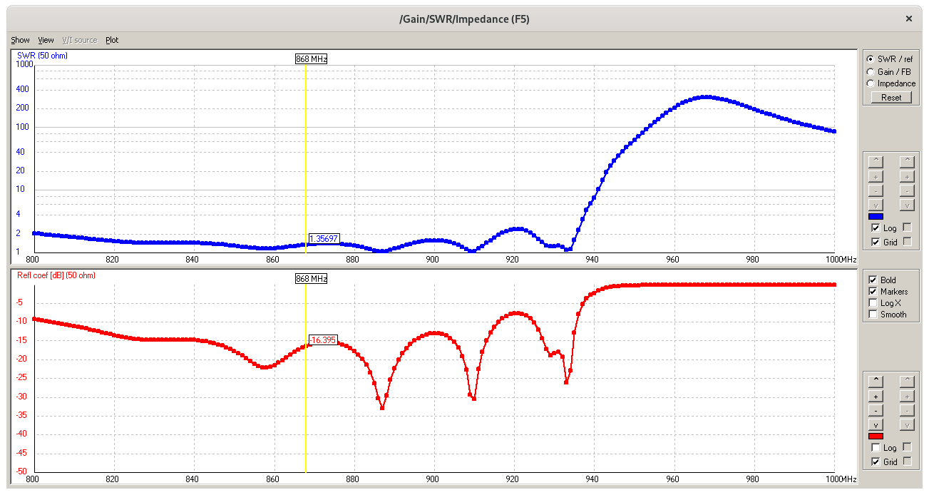
A DL6WU-yagi design antenna has a very recognizable course of the SWR and impedance. Below the value from the NEC simulation and the measured value. The antenna is quite broadband, but above a certain frequency the whole radiation pattern collapses. I specifically chose the SWR display because this effect is also slightly more dramatic in the graph.
NEC simulation. Note the blue line and Note that the frequency cutoff starts at 940 MHz.
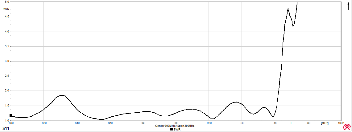
The measured values by the VNA. Note that the frequency cutoff starts at 960 MHz.
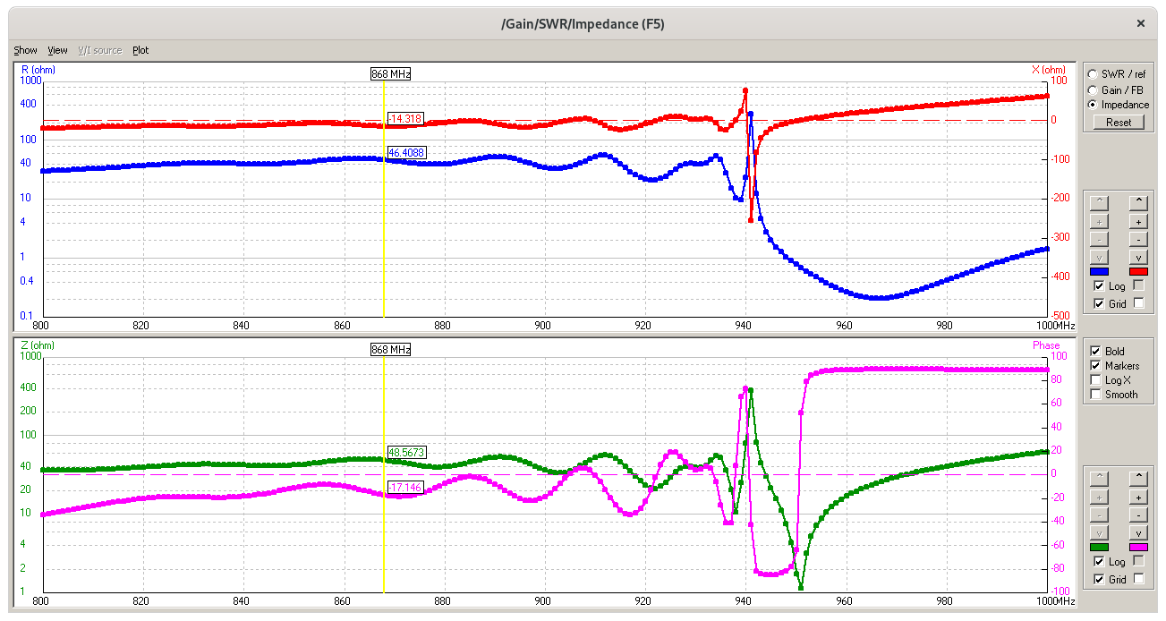
NEC simulation. It's about the green line Note that the frequency cutoff starts at 940 MHz.
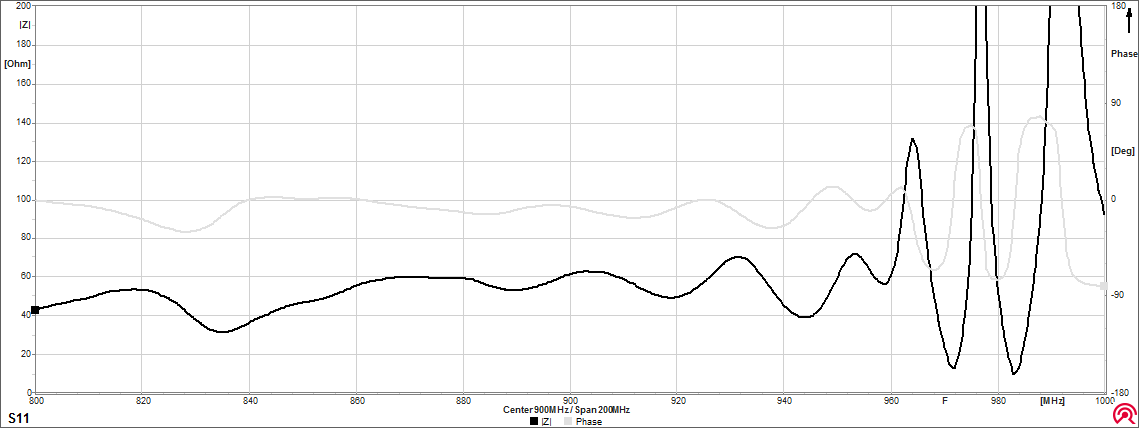
The measured values by the VNA. Note that the frequency cutoff starts at 960 MHz.
The measured value corresponds to the calculated values except that the measured values are shifted 20 MHz higher in frequency.
Gain
My point was to measure the gain difference between 868 MHz and 903 MHz. It was not about absolute gain of the antenna.
The VNA has a built-in frequency generator. I first used this generator to generate a signal on a broadband vivaldi antenna. Subsequently, the signal with the yagi antenna was received on a spectrum analyzer. Then I realized it was more convenient to do an S21 measurement with the VNA by transmitting a frequency sweep of 800 - 1000 MHz on the vivaldi antenna and receiving again with the VNA on the yagi antenna. This worked fine.
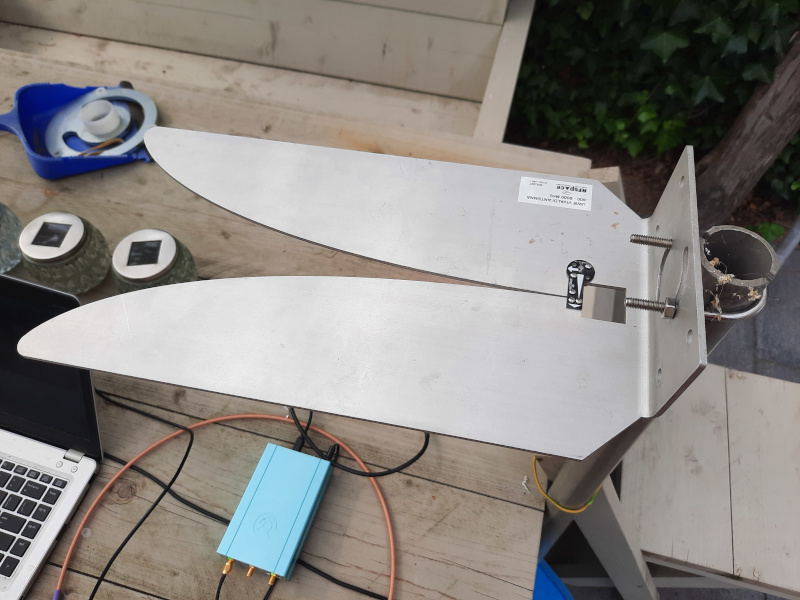
The vivaldi 'reference' antenna from RFSpace.
It is clear that the yagi antenna also works at 903 MHz. The measurement indicates 1 dB more gain even at this frequency.
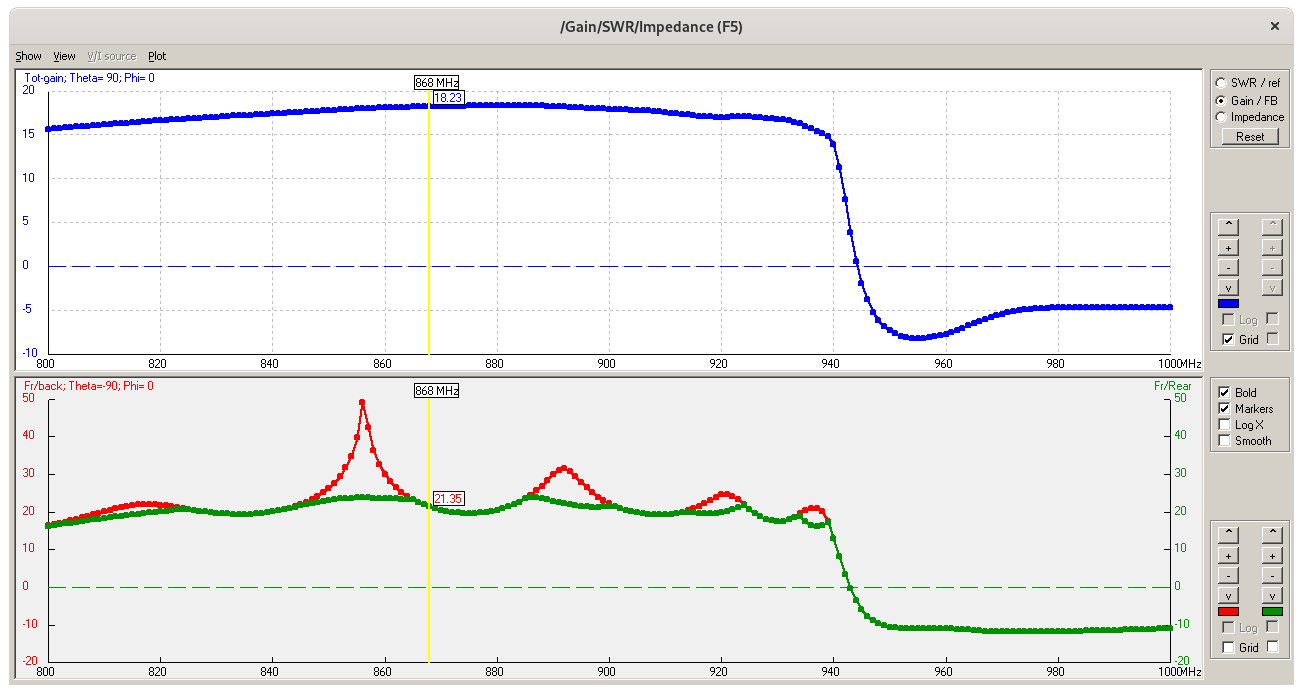
NEC simulation. The blue line in the top window shows the gain between 800 and 1000 MHz. Note that the gain drop starts at 940 MHz.
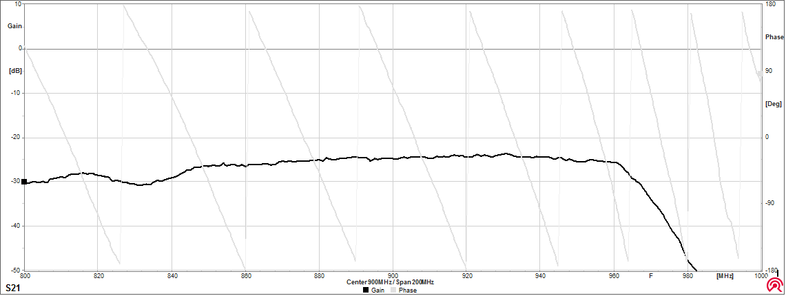
The S21 measurement. The gain represents the signal loss between the transmit and receive antennas that were placed 5 meters apart. Note that the gain drop starts at 960 MHz. This is 20 MHz later than the simulation.
In an absolute sense, the measured value at the receiving antenna is in line with what you would expect. 0 dBm minus a path loss of 45.2 dB. The antenna gain is 18.2 db. I assume the gain of the vivalidi antenna is around 2 db. I have compensated for cable losses in the calibration.
0 (dbm output) + 2 (db tx antenna gain) - 45.2 (db pathloss) + 18.2 (db rx antenna gain) = -25 dBm.
The antenna can be used between 850 and 930 MHz.
Boom Correction
The antenna is designed for 868 MHz. However, the measurements show that the entire design frequency has shifted up by 20 MHz.
Obviously I forgot to apply a boom correction to the element length. The plastic holder and the boom form a kind of short circuit on the element. This can be corrected by making the elements a little longer. I should have made the elements about 3.2 mm longer than the online calculator indicated.
More on boom corrections.
HOME | Go Back