FM-DX Antennas
(2011-06-27) PE1ITR
7 elements 89MHz LFA Yagi
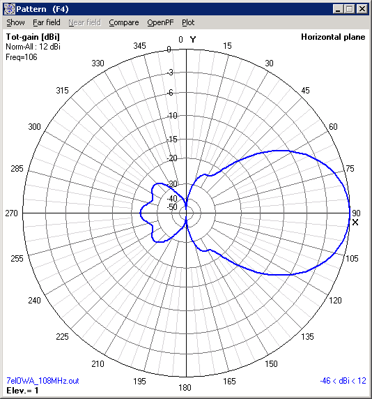
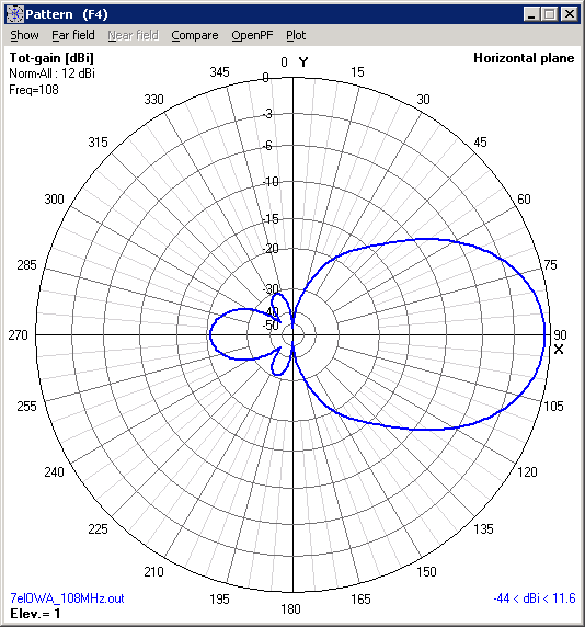
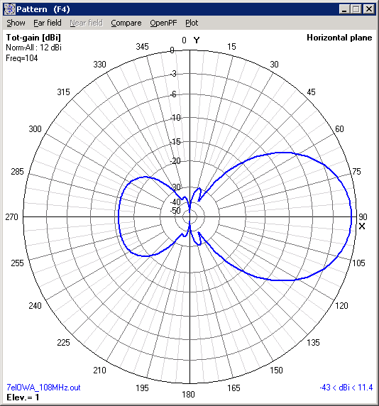
7 elements 107MHz OWA Yagi
7el 89MHz LFA Yagi
This design is based on this antenna: A 7 element LFA Yagi for 70MHz with a 6.89mtr boom.
I rescaled the values for low part of band 3 and simulated (with 4nec2) the result. Just for fun and to see I could manage this.
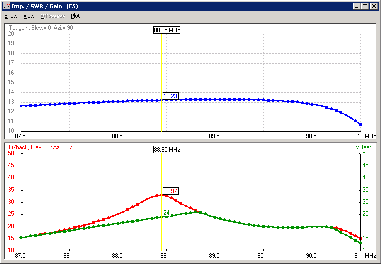
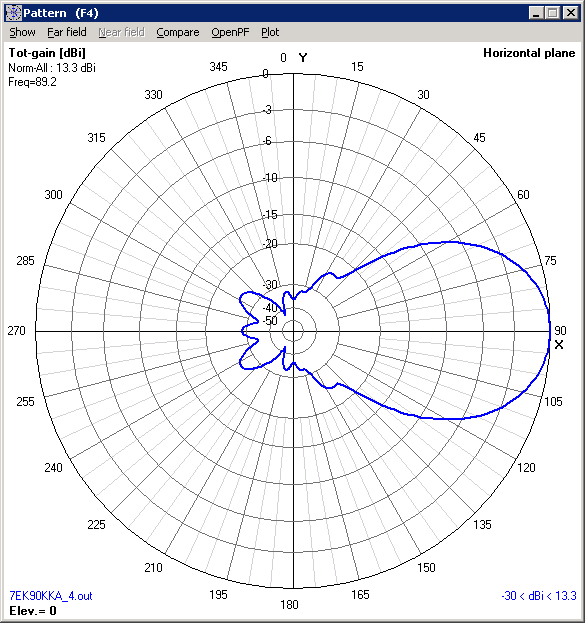
Bandwidth: 87,5 - 90,5MHz
Design
| Boom | Elements | Half Elements | Diameter |
| R | 0 | 1654 | 827 | 10mm |
| S1 | 215 | 1380 | 690 | 12mm; loop end 10mm |
| S2 | 520 | 1380 | 690 | 12mm; loop end 10mm |
| D1 | 958 | 1546 | 773 | 10mm |
| D2 | 1860 | 1498 | 749 | 10mm |
| D3 | 2993 | 1472 | 736 | 10mm |
| D4 | 4249 | 1448 | 724 | 10mm |
| D5 | 5384 | 1420 | 710 | 10mm |
First tests 2010-12-31
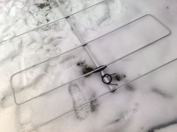
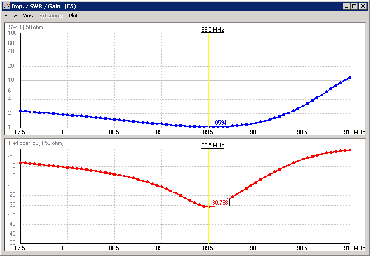
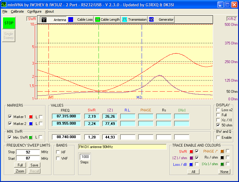
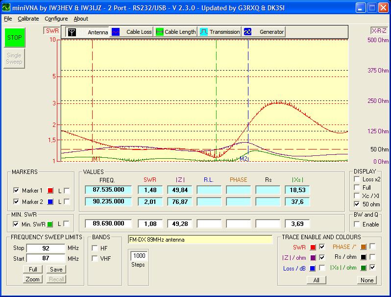
The first results. Adjusting the dipole loop is important. First I had a bad swr and a second even better dip around 93 MHz but with some tuning it became better.
I will improve this when wetter is better.
The antenna is lower in frequency than calculated.
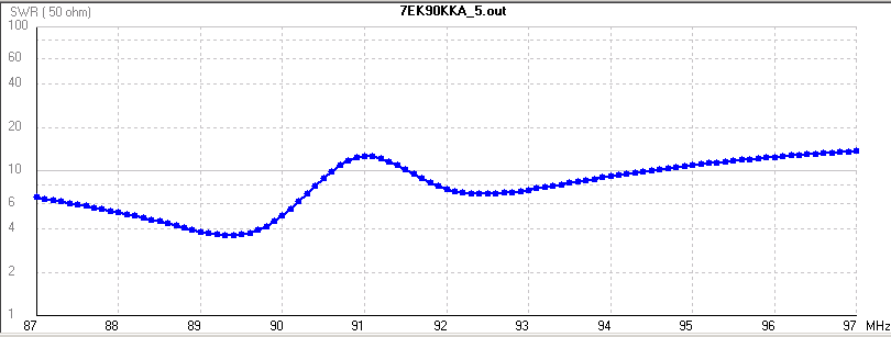
Funny. I found the error and could more or less simulate it. Below the simulated swr graph with the loop error. It seams that the loop is a few centimeters to small.
Changed dipole loop
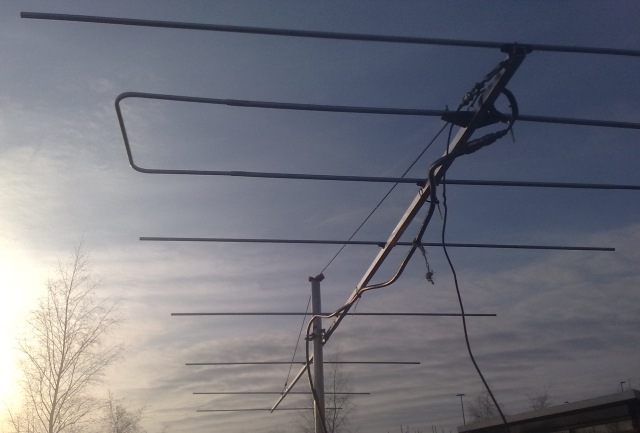
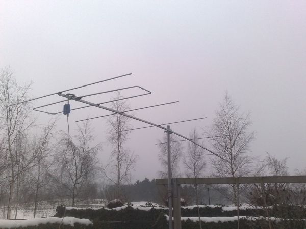
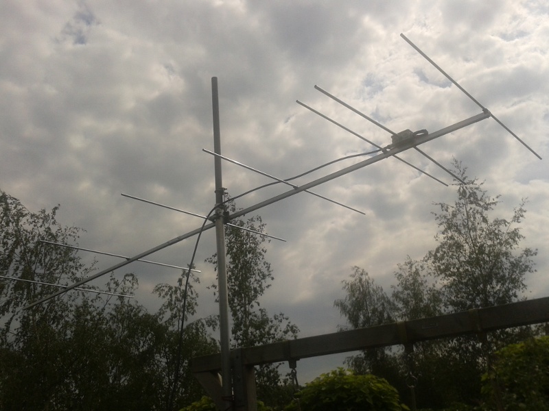
Here are pictures of the LFA yagi in action.
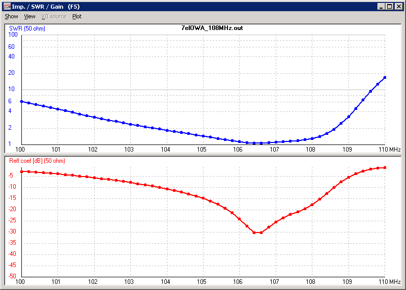
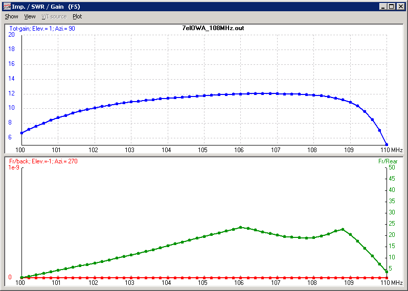
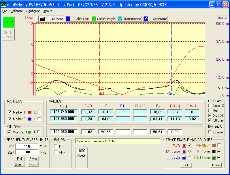
7 elements 107MHz Yagi OWA yagi antenna
Data and pictures of the enginering model.
Bandwidth: 104 - 108 MHz
HOME | Go Back