Simple Interferometer
(2009-08-20) PE1ITR
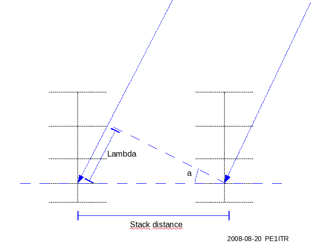
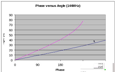
The image below shows the operation of the interfometer. The phase difference of the signal between the two antennas is measured. This phase difference is converted to lambda.
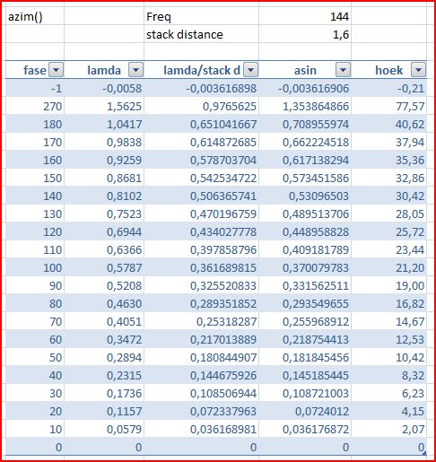
The phase difference is measured with Spectrum Lab software. It has a built in function (azim()) that the phase difference between left and right channels can be calculated.
The table translates the measured phase difference to the received corner with the distance between the antennas and frequency as parameters.
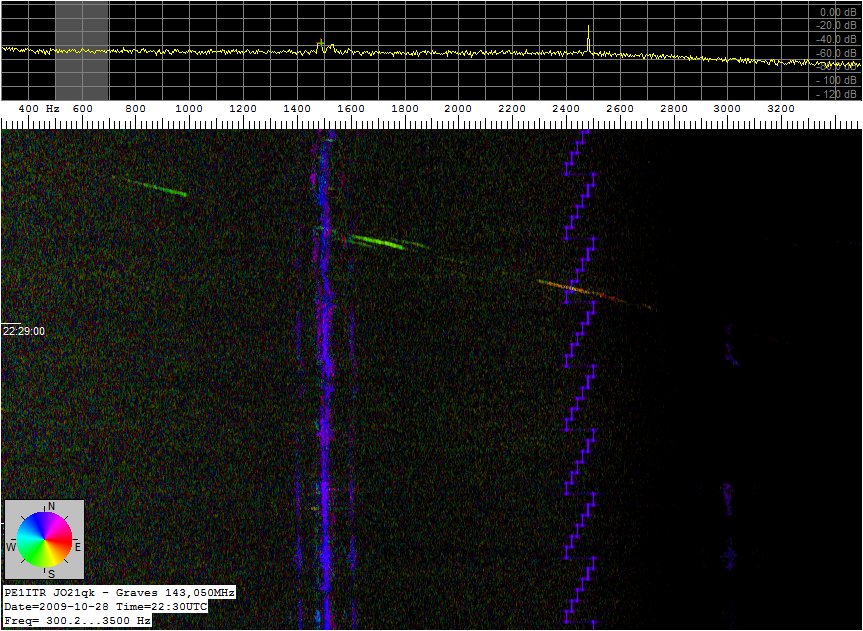
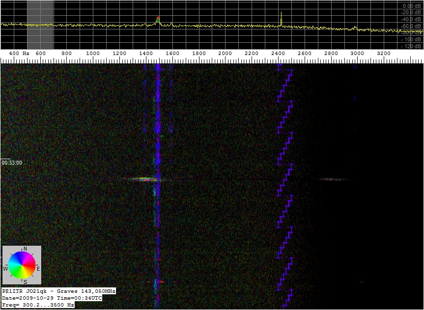
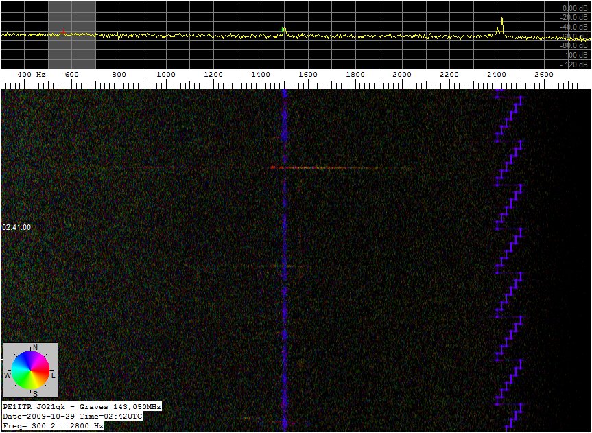
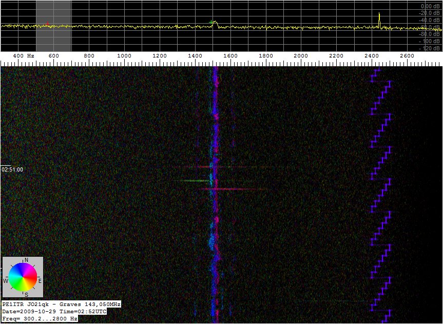
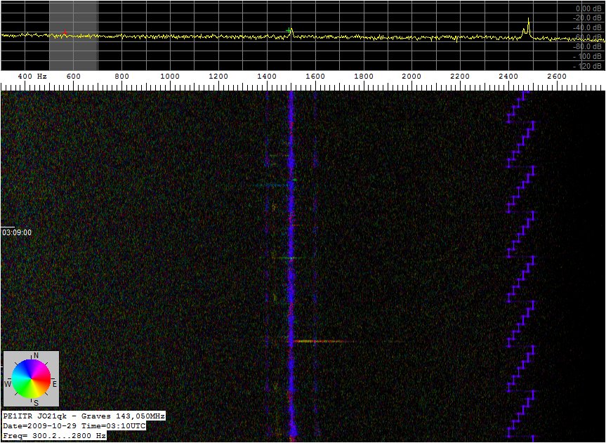
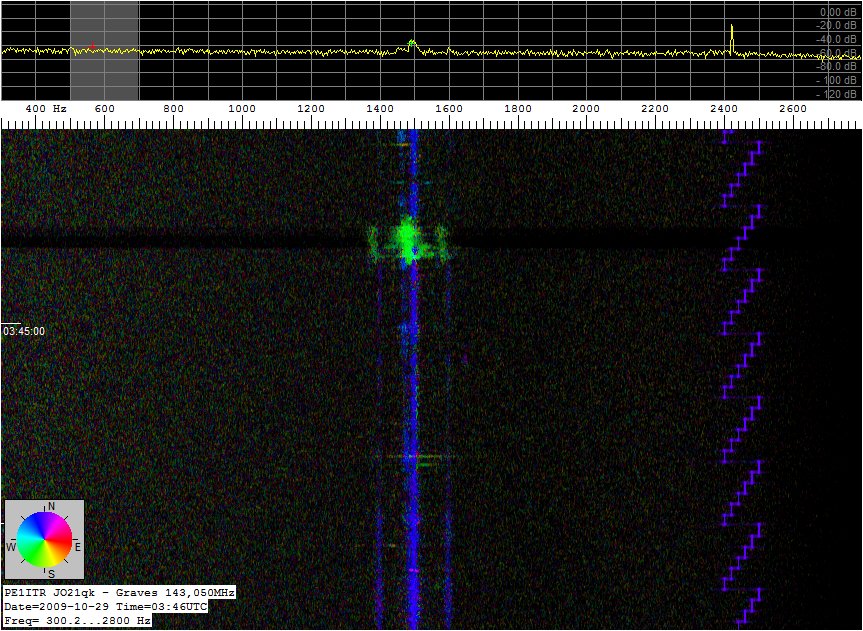
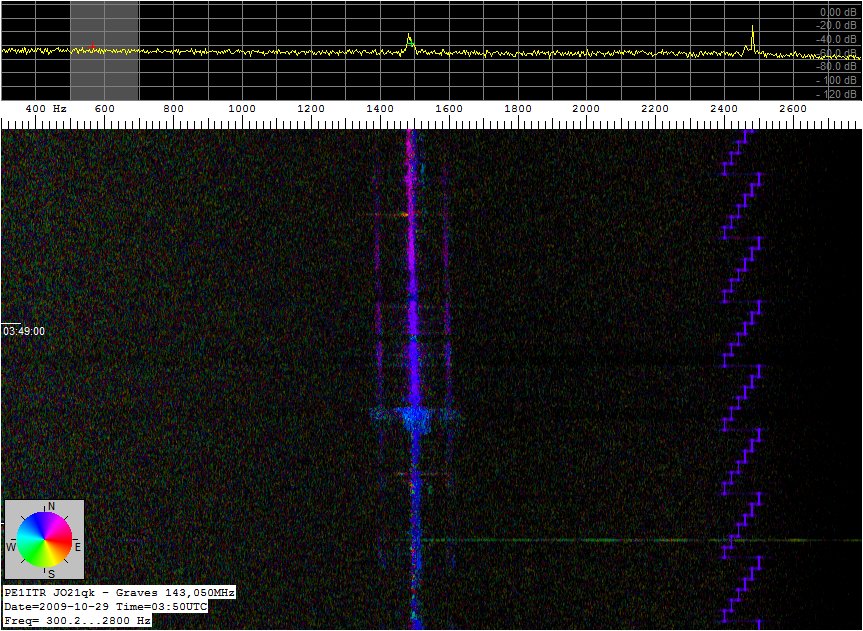
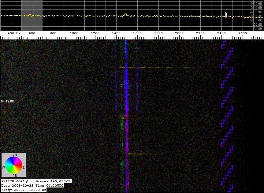
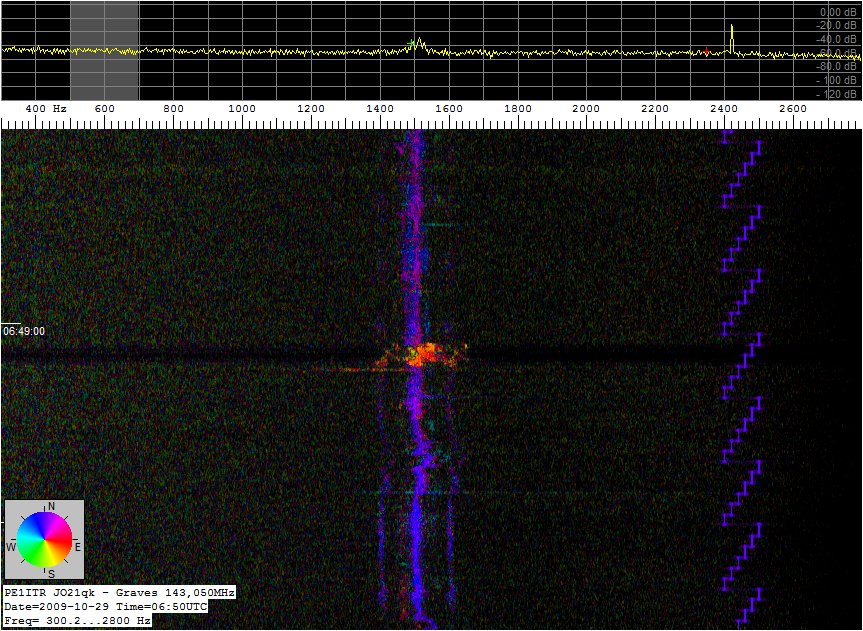
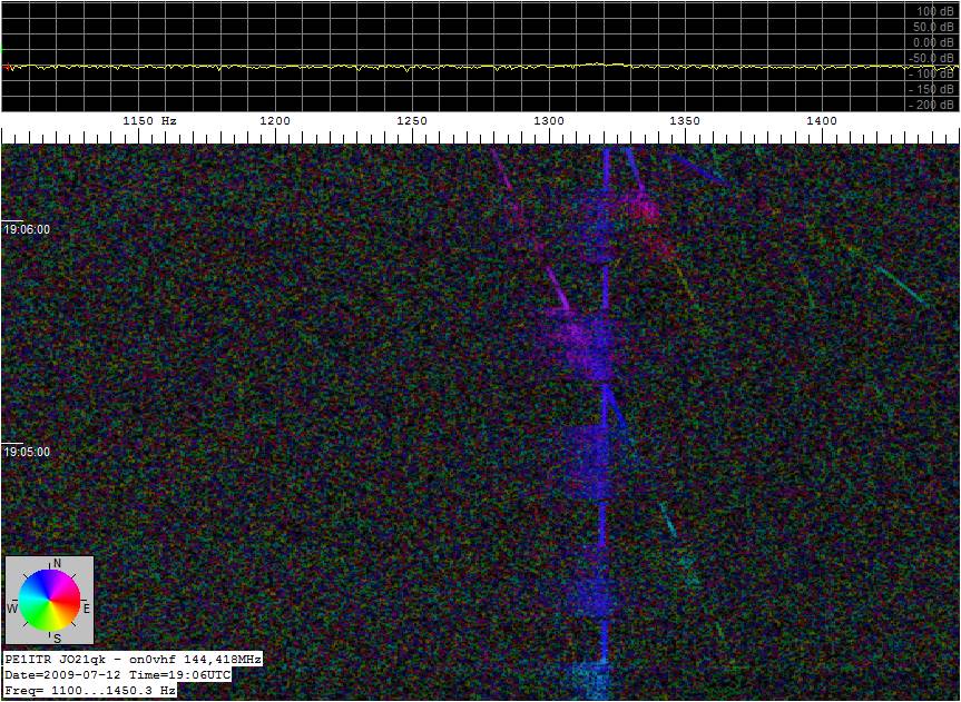
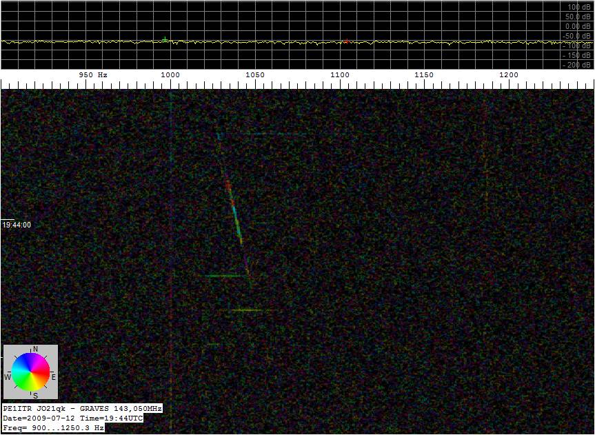
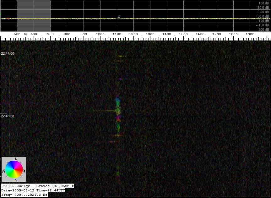
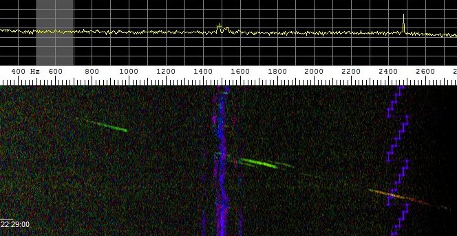
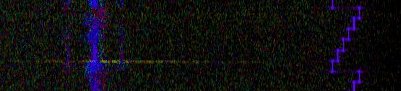
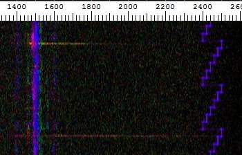
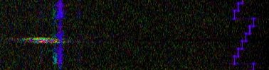
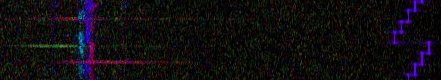
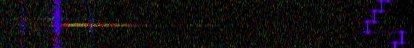
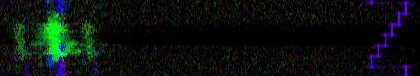
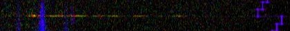
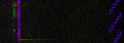
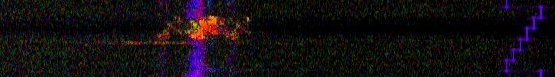
The color in the waterfall pictures shows the phase difference between the signals. The dial in the waterfall images does not reflect the actual corner but again the phase difference.
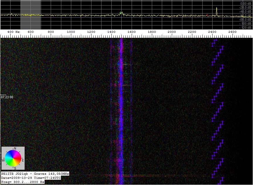
The picture below is a airplane reflection and the direct tropo signal from the beacon on0vhf on 144.418MHz. The plane reflection color changed slowly over time. The antennas were aimed at the beacon so the phase difference of the beacon was zero. The picture shows a blue line. Also shown is that periodically the callsign of the beacon is transmitted by FSK modulation.
Interesting to see that the received reflections of an object during the switching of the GRAVES radar beam does not come from the same direction. Or better it has an effect on the received phase. There are apparently other effects that play a role. The radar has a 4 beams scanning. This calls for further study. :-)
2009-10-28
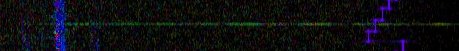
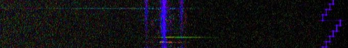
Stack 3.3 meter. 2x10 el yagi. Ambigity in phase detection.


HOME