VHF Radar Experiments Orionids
(2020-10-25) PE1ITR
Earlier I had written here about my VHF radar experiments. So far I have received backscatter reflections from airplanes and meteors. This page focuses on two meteor reflections that I received on October 21, 2020 during the Orionids meteor shower. A 10 element yagi was used in a direction perpendicular to the Radiant of the shower. I calculate at what distance these meteors must have been.
The total number of meteor backscatter reflections in the shower actually disappointed me. I expected more. It is known that backscatter reflections are less strong than forward reflections and this may be the result of my small system. Military VHF Radars intended to detect stealth aircraft have 16 db more output and use antenna systems with 12 db more gain than in my case.
Below screenshots of the two strongest reflections.
Reflection 1: 2020-10-20 23:27:16 UTC 144.510 MHz. 1200 millisecond burst.
Reflection 2: 2020-10-21 03:59:02 UTC 144.510 MHz. 400 millisecond burst.
Characteristics of the radar
The TX signal is a 4 ms pulse. The repetition rate is 25 Hz, which gives a period of 40 ms. The receiver is on for 34 ms. 2 ms is reserved for switching from rx to tx and vice versa. The tail going from tx to rx is 200 microseconds. The picture below shows the timing.
The position of the TX transmission pulse can be shifted. It should be as close as possible to the point where the radar starts receiving. To start with, I chose a TX pulse of 4 ms to keep the bandwidth within limits. This corresponds to a "dit" in a telegraphy speed of approximately 100 words per minute. In the old days of Meteor scatter High Speed Telegraphy (HSCW), speeds of 200 WPM or more were used.
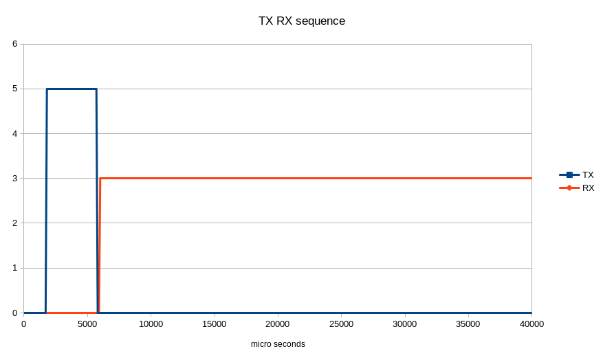
This is the sequence of the 40 ms period.
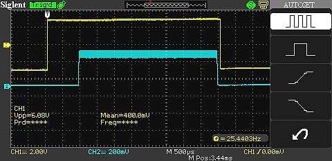
The picture shows the sequence of the TX pulse. The yellow line is the sequencer that switches the coax relay for TX/RX. When the yellow line is high, the relay is on TX.
The blue line is the RF measured at the output of the SSPA. There is 200 microsecond between stopping the TX and switching to RX.
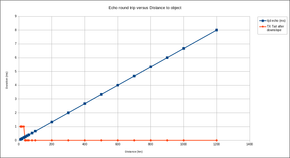
The graph below shows the time between TX pulse and echo against the distance. From the graph it can be deduced that objects must be at least at a distance of 50 km to see a 100 micosecond part of the 4 ms echo. The full 4 ms echo is only visible when the distance between the object is 630km or further.
Calculation of distance to meteor reflection
The distance is calculated by viewing an audio recording of the reflection in the software program in Audacity. By zooming in on the audio level window, the number of samples can be counted between the end of the TX pulse and the end of the received pulse.
The sample rate of the audio recording is 48000 Hz. That is 1 sample per 0.0208333 milli second. The duration of the echo is calculated based on the number of samples. The duration is 2x the distance.
Formula: Distance (km) = ((Number samples * one sample duration (ms)) / 1000 * 299792.5 (km/s)) / 2.
Reflection 1
I measure 246 samples. That's a round trip of 5,125 ms. This corresponds to a distance of approximately 768 kilometers.
This is the audio recording with the same reflection twice in succession because the original IQ file was played in a loop: ms2110-4-2-audio.wav

We see 4 periods and also 4 reflections in the picture. The distance between the end of the TX pulse and the end of the received pulse is 246 samples. This is the lighter part in the picture.
Reflection 2
I measure 256 samples. That's a round trip of 5,333 ms. This corresponds to a distance of approximately 800 kilometers.
This is the audio recording.: ms2110-8-2-audio.wav
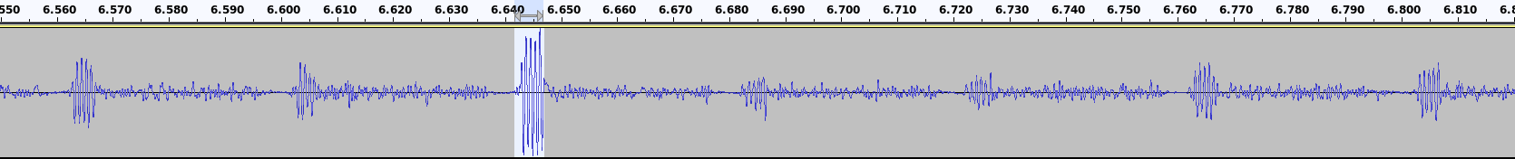
We see 7 reflections in the picture. The distance between the end of the TX pulse and the end of the received pulse is 256 samples. This is the lighter part in the picture.
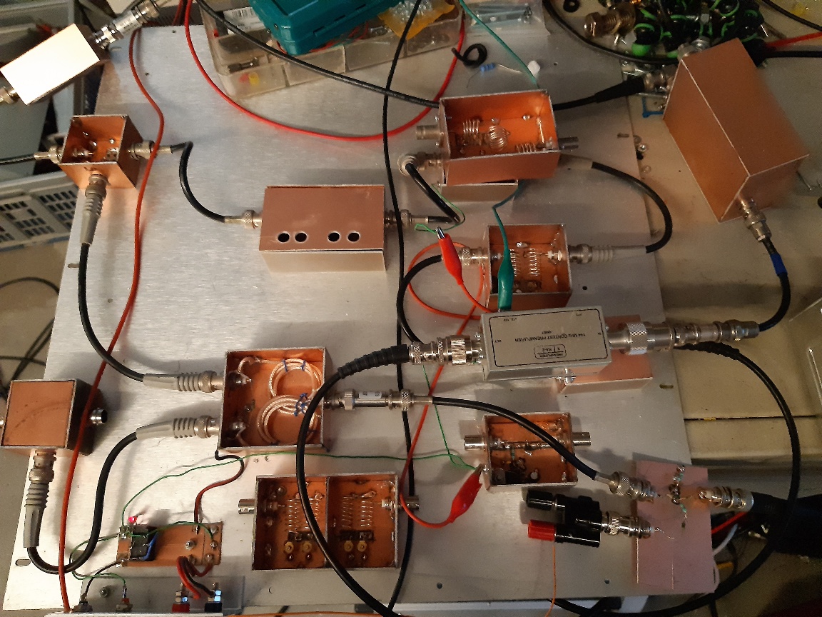
Receiver
I am using an SDR-IQ with Linrad as the receiver. There is a converter in front of the SDR-IQ. From the pin diode coax relay, the circuit is as follows. An extra pin diode switch, then the 144 MHz pre-amp followed by an amplifier, band filter, amplifier, band filter and mixer. The LO is a 120 MHz signal. The LO signal is also switched by the sequencer. 144 - 120 = 24 MHz goes through another pin diode switch, then a 24 MHz low pass filter with also a 2 MHz high pass filter.
It turned out that the pin diode switch in the 24 Mhz MF part causes strange effects in the SDR. This extra high-pass filter solved that. Below a picture of the 80s style setup. It looks dated but is modern and modular :-).
HOME | Go Back