VHF Radar Experiments 2020
(2020-09-01) PE1ITR
Inspired by the SM5BSZ website, I started building a radar system at 144 MHz in 2016. This actually turned into a failure. Learned from it. Now in 2020 the experiment picked up again and started building a good antenna pin diode relay. Also another approach to control the pulses and timing. Despite a few problems to be solved, still managed to achieve a reasonably working system. Some notes on this page.
PIN diode antenne switch
Design
The design is copied directly from SM5BSZ as described on its website.
In the beginning I thought that the switch could be built with parts that I had lying around. For example, I used 75 ohm cable for the quarter wave coax stubs. Don't, because it will cost you at least 5 dB of isolation between RX and TX.
I have added a circuit with a Power MOSFET to switch the diodes, transmitter and receiver with the function generator.
LTspice simulation
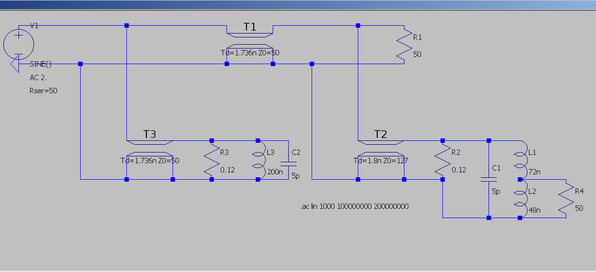
In order to better understand the operation of the switch, I simplified the circuit in LTspice. In this way the values can easily be changed. The current through the diode and thus the resistance of the diode and the impedance of the coax is an important factor.
The PIN diodes that are actually included in the circuit have been replaced in the simulation scheme by ordinary resistors. In RX mode the resistance is high, 1k5 ohms. In TX mode current flows through the diode and then the resistance is low, 0.12 ohms.
TX mode
This is the TX mode. Current flows through the pin diode. Therefore R2 and R3 are 0.12 ohms. This resistance should be as low as possible.
The impedance of the coax stub between the antenna and the RX port is an important factor because it also determines the isolation to the RX port. In TX mode, the resistance should be as high as possible at the Antenna port. The resistance at the RX port is very low. The impedance of the coax must be high. I am using a homemade 127 ohm coax.
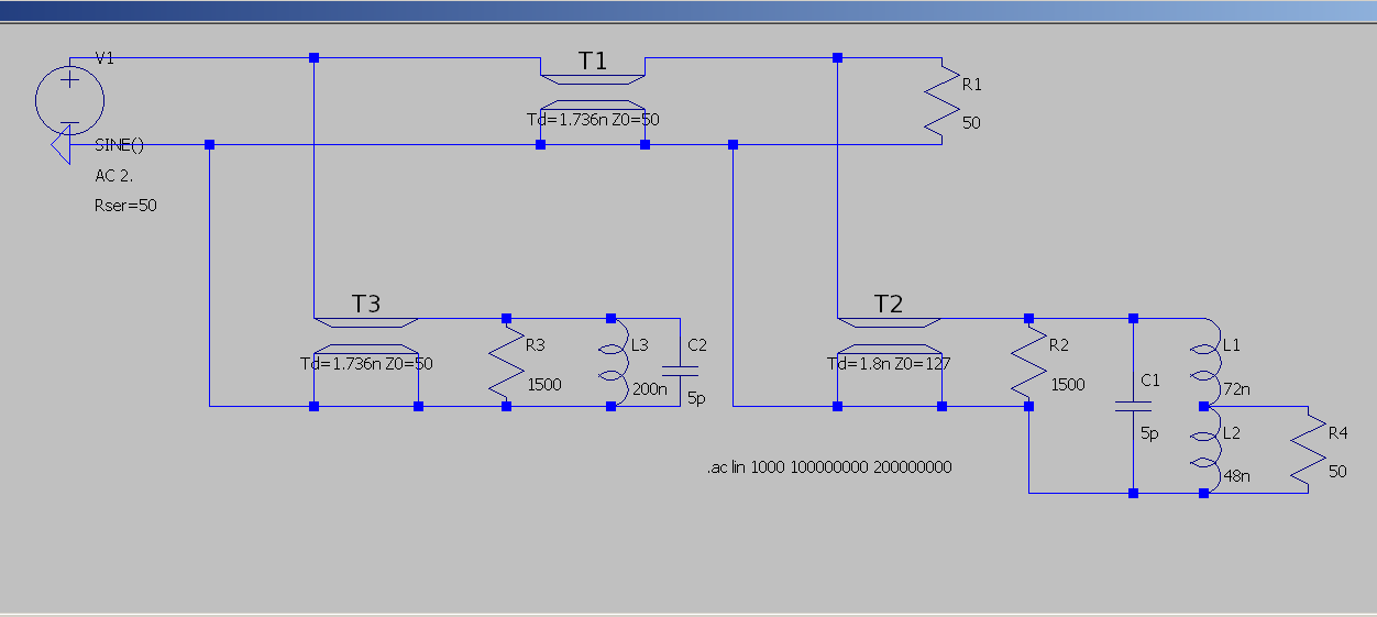
RX mode
This is RX mode. No current is flowing through the diode. R2 and R3 will be 1500 ohms. The attenuation between antenna and rx port is low. The antenna port sees 50 ohms. Due to the 127 ohm coax, the impedance at the top of the coil will be approximately 127 ohms. By means of the tap to the RX port it is transformed back to 50 ohms.
Another point is the isolation between TX port and RX port. The SSPA produces noise that you hear on the receiver during reception. To prevent this as much as possible, there must be sufficient insolation between TX and RX port in RX mode. The coax stub and LC circuit at the TX port takes care of that. In the original scheme, 100 ohm coax is also used for this. But through simulation in LTspice I found out that it is better to use 50 ohm coax for this. The attenuation is then at least 5 dB better. Practice also showed that this was a good improvement.
Construction
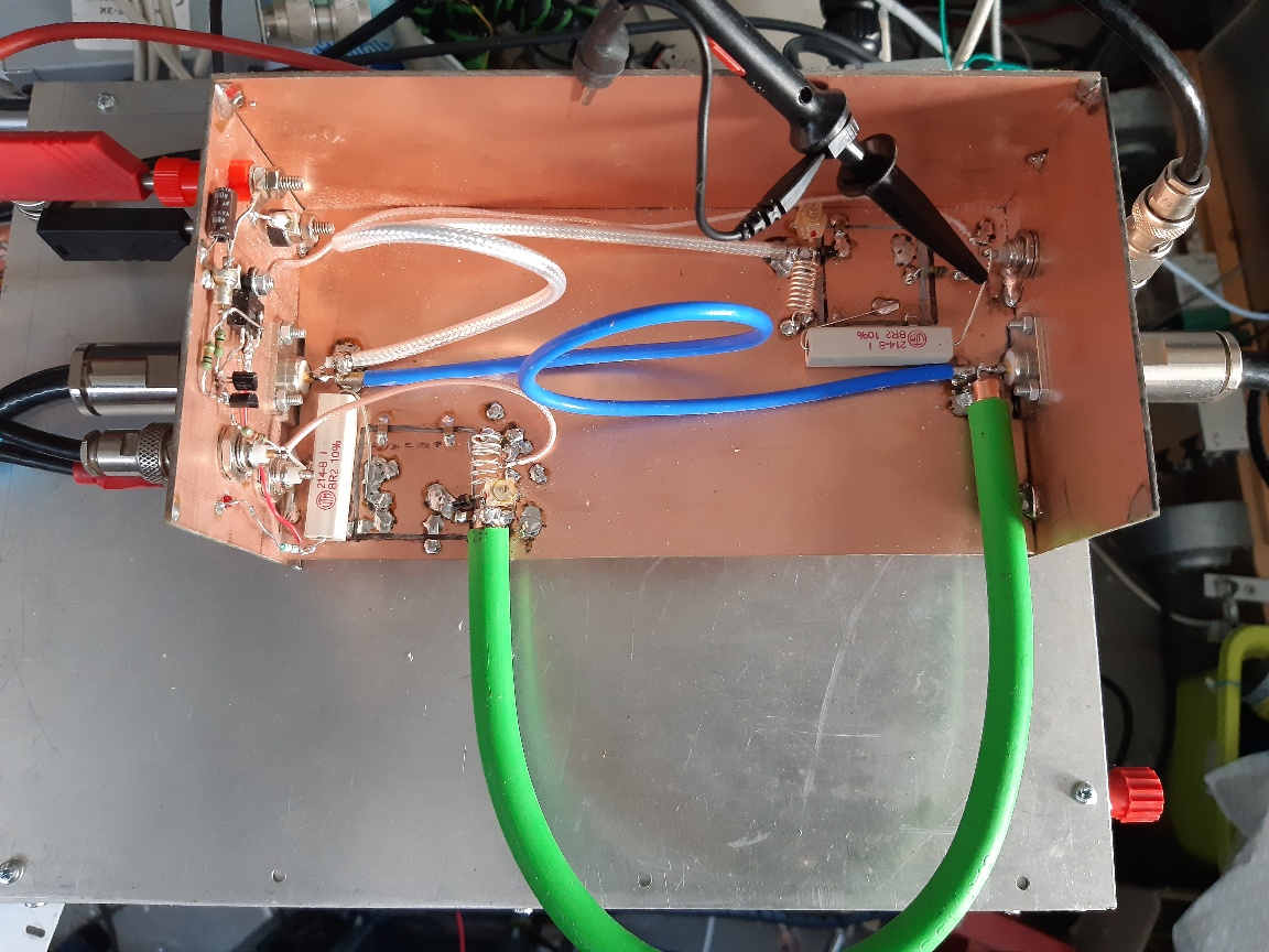
The photo below shows the construction of the pin diode switch. It is a first experimental setup. On the left side an N-connector for the transmitter. Also a BNC for the RX port where the pre-amp is connected. Then two banana plugs for the 12v power supply. And an extra BNC connector that connects to the sequencer PTT. In my case the function generator. With two BC547 transistors and an IRF Power MOSFET, the current is switched through the diodes. This switching current is also fed to the transmitter on the right side via a BNC connector in order to switch the control stages. An inverted signal also goes to all receiver stages that are also switched.
On the right are also the N connector to the antenna.
I am using a UM4001 pin diode. Approximately 800mA runs through each diode in TX mode. I have not (yet) applied a negative 12v to the diode to further increase the resistance in RX mode. The connecting wires of the diode must be cut short
. The diode is decoupled for RF on the 12v side with a number of ATC capacitors to ground.
The following values are measured with my miniVNA:
| Mode | Port to Port | Atenuation (db) |
| TX | TX to RX | 40.1 |
| TX | TX to Antenna | 0.33 |
| RX | TX to RX | 35.0 |
| RX | Antenna to TX | 0.62 |
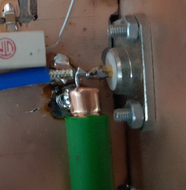
High impedance coax
I made the quarter wave coax pieces from the well-known green 75 ohm coax that is used in cable TV networks. I pulled out the inner wire and replaced it with a 0.8mm wire. This increases the impedance to 127 ohms.
atlc (Arbitrary Transmission Line Calculator) by Dr David Kirkby is a nice software program to calculate this. You can also calculate the effect when the core wire is slightly off center. This is in my case not too bad.

Generating Pulses
A Siglent SDG1050 function waveform generator is used as a PTT sequencer and to generate the transmission pulse. Output channel 1 is used for RX / TX switching and controls the pin diode antenna switch, receiver and transmitter driver stages. Output channel 2 is used to generate a pulse at 9 MHz that is used to generate the actual transmit signal. I use my old DIY tranceiver as a control transmitter. This transceiver has 9 MHz as intermediate frequency.
Short pulses are not sent out to keep the bandwidth narrow. The pulse width is adjustable and in the test set to 4 milliseconds. This is exactly 36000 periods on 9 MHz. The repetition frequency is 25 Hz. This gives 36 milliseconds without transmission.
1 millisecond is used for the sequencer ptt. Switch from Tx to Rx is set to 150 microseconds. This means that 850 microsecond is used to go from RX to TX. 35 milliseconds is used to actually receive signals.
The 4 ms tx pulse can be shifted in the time frame of 5 ms. This allows the TX to RX switch time to be set from a few tens of micro seconds to 500 microseconds.
Below is a picture of the oscilloscope screen. The x-axis is set to 500 microseconds / div. The signal from the RX / TX switch is on the first channel (yellow line). The second channel (blue line) shows the output of the transmitter measured after the last stage.
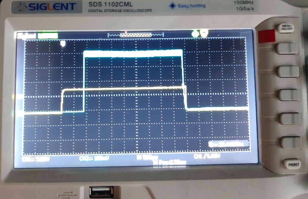
With these switching times I could see echoes from reflecting objects from 40 km away.
Block Circuit Diagram
Block circuit diagram will be added.
Transmitter: Homemade + Siglent SDG1050. Amplifier BLY88 in class C operation. SSPA with 2xMRFE6VP6300.
Receiver: SPF5189Z Pre-map. Converter from 144 MHz to 24 MHz. SDR-IQ and linrad.
Results
First test
The picture below shows the first test with the above setup. The output power of the transmitter is now 400w. The radar pulses are broadcast on 144.510 MHz and the bandwidth is almost in an ssb signal bandwidth. < - Note: In retrospect, this turns out to be incorrect. The bandwidth is much wider. I estimate that the -40 dB levels are at +/- 30 kHz. So the signal is 60 kHz wide.
The signal strength window shows the TX pulses with the pause for reception in between.
I can also listen to beacons "simultaneously" while transmitting. You see in the upper waterfall ON0VHF, F5ZAM. I can also continue to receive DB0MMO a beacon 350 km away. The signals sound funny. SSB signals are well understood and even FT8 signals decode fine despite being chopped. So it seems to work ...
There is still work to be done. At this moment the noise floor of the receiver rises by at least 2 db when only the sspa is turned on. This costs the receiver's sensitivity. The feedback from the transmitter is also very dependent on where I put the receiver on the table. This can be solved. Actually I want to make it so that I no longer see my own broadcast or at least very weakly on the receiver.
In the first test I occasionally hear a second radar tap in the audio, which then has qsb, as can also be heard with airplane reflections.
Echo's
The first radio echoes have been received! I am using a 10 elements yagi at a height of 4m.. The two screenshots below show reflections against aircraft. I estimate that the distance to the plane was about 100 km. That may be correct because at the same time B747 Cargo planes flew past me over this line.
I have done the necessary to make the pulses from my own transmitter inaudible. These interfere with the reception quite a bit. In the first screenshot, these pulses were still 20 dB above the noise. But after I added extra diodes to silence the receiver in the TX periods, those pulses are almost gone. More on that in a future post.
Another problem is noise from the receiver's own system. This comes from SSPA but is unpredictable and therefore difficult to get rid of. The increased noise varies between 2 and 6 dB when the transmitter is switched on, but depends on the setup, how coax cables are laid. The length of coax cables and so on. Here still has to be sorted out.
It shows its own TX pulse at -32 dbm. This pulse is extended by less than a millisecond with the reflection at -25 dBm.
This is a similar reflection to the screenshot above. However, now I suppressed the TX pulses much further on the receiver. You now only see the reflection.
The next goal is to receive Meteor Reflections. These should be easier to see because the distance is greater. Here is my report for the Orionids.
HOME | Go Back